This thread has been locked.

If you have a related question, please click the "Ask a related question" button in the top right corner. The newly created question will be automatically linked to this question.

EK-TM4C129EXL: Glitch on SSI1 Serial Out Pin in Freescale Modes

Part Number: EK-TM4C129EXL
Other Parts Discussed in Thread: LP5890, TLC6983

Hi,

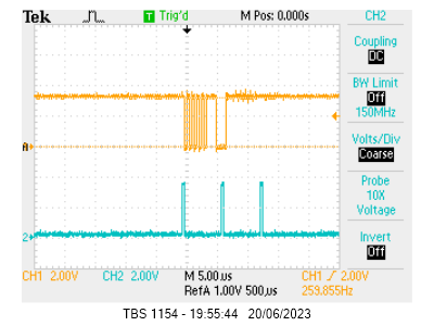
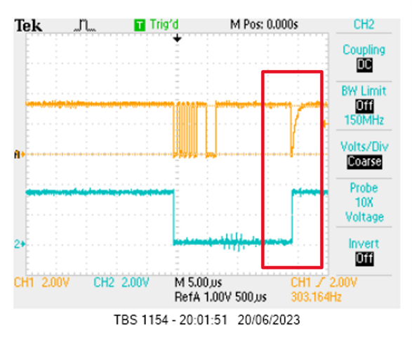
When using SSI1 as a master with the mode as either SSI_FRF_MOTO_MODE_1 or SSI_FRF_MOTO_MODE_3 I see a glitch to 0V on the serial out pin at the very end of the frame, just as FSS returns high. I do not see any glitch when using SSI_FRF_TI (TI continuous mode). I am using a 10K resistor as the pull up for the serial out pin. The pin configurations are those for SSI1 from the TI PinMux tool with no further modifications.

Is this due to me doing something wrong please?

Thanks,

Matthew

  • Hi,

      Are you generating the Fss using the SSI module or the Fss is generated by a GPIO? It seems to me the CS signal prolongs much longer than supposed to compare to the data pin. Can you also add the clock to the scope to have everything in perspective?  If the glitch is outside the active chip-select, it should not cause the slave device to misinterpret the glitch as a valid data. Can you confirm the slave is receiving the data correctly? Normally, there is no requirement to add a pullup on the MOSI pin but I don't think it will hurt. What I think is that after the Fss is de-asserted, the data is basically undefined, could be in tri-state. Depending on the capacitance on the trace and your 10k pullup resistor, it can take some RC delay to pull up to 3.3V.  

  • Hi Charles,

    Thanks for your quick response.

    1. FSS is generated automatically by the SSI module, the frame just happens to contain a lot of logic 1’s! You can verify this from the other trace I sent.

    2. I agree that normally this would not present a problem as there were no clocks during or after the rogue pulse. However I happen to be using this with a PWM generated continuous clock to drive LP5890/TLC6983 LED drivers, so this pulse does get seen and stop things working properly. Because the TI synchronous mode shows no such problem it works perfectly well with the continuous clock and I can continue using this mode. I was just trying these modes out of completeness, and if they don’t work in this application it is not a problem.

    3. I added the pull-up as I read the pin is tristated when idle, so didn’t want it floating.

    4. Thanks for pointing out the Q = undefined region. I hadn’t noticed that. It could well explain what I was seeing.

    I really just wanted to be sure this was not something I had done wrong, it seems it is expected behaviour of the SSI module.

    Regards,

    Matthew