This thread has been locked.

If you have a related question, please click the "Ask a related question" button in the top right corner. The newly created question will be automatically linked to this question.

TMS470PLF111 ARM7 HAL Code Gen support and technical manuals for this device

Other Parts Discussed in Thread: HALCOGEN

Had to select unknown part number because it wasn't in the drop down list... TMS470PLF111.

Looking for any technical manuals for GIO, CLass 2, watch dog, FMPKEY, flash wrapper, and watch dog, J-tag

Also looking for .cnf file for HAL Code Gen

Thanks,

Jamie 

  • Hi,

      This is an EOL'ed device. Its architecture is similar to https://www.ti.com/product/TMS470R1B1M for which you can find the TRM. There is no HalCoGen for this device. 

  • Yes but there is so many differences I am having hard time reading the flash and ram via J-tag, the offsets are randomly changing. And I cannot write to GIODSETC at address 0xFFF7BC58.   I also have no information on the FMPKEYs for this device. Is there no archive for the TMS470PLF111 TRM ? it must have existed at some point. This is a old board, I cannot change the processor, I just want to add some new functions to the existing code and architecture.  

  • This is what I can find for this device. As this device is EOL'ed and we don't have knowledge to support this device on e2e forum. 

    platform_F05_flash.pdfRTI.pdfGIO_Platform.pdfPlatform_C2SI_book.pdf

  • OK Thanks, I cannot access flash ECC how do I read it? or unlock it? I can read everything else! 

    Also how do I toggle output pin GIOC[4] ?  Can I do so via J tag, by writing values to the GIO register?


  • OK Thanks, I cannot access flash ECC how do I read it? or unlock it? I can read everything else! 

    You need to go through flash controller user's guide which was attached. Go to section 4.3.2 where it describes ECC memory map. ECC is memory mapped to an 4Mb offset from the main flash. 

    Also how do I toggle output pin GIOC[4] ?  Can I do so via J tag, by writing values to the GIO register?

    Each GIO port data register has three alias addresses, an address to do write arbitrary values, an address to only set bits, an address to only clear bits. I suppose you mean GIOC[4] as to clearing bit 4 of a GIO port.  If you want to clear bit 4 of a port and not affect other bits, you can write 0x10 to GIOCLR register. If you want set bit 7 and not affect the states of other bits, you can write 0x80 to GIOSET register. Refer to the User's guide if you are new to this processor. 

    You can change the GIO in your IDE register window through JTAG. 

  • Ok Great thanks, regarding the GIOC all my values are ontop of the base GIO register..

    The existing code (not written by me) is bringing GIOC[4] low which provides ground to a resister connected to 12 volts. Multi meter reads 12 volts connected to this pin. I want to turn it off via J-tag, so the voltage goes to zero on my meter.   

    I previously tried:

    0x58 -> GIODSETC = 0xFF //set all bits 

    0x4C -> GIODIRC = 0xFF //config port 2 (GIO port C) as output 

    0x58 -> GIODSETC = 0x10 //toggle pin 4 

    0x5C -> GIODCLRC =  0x0000001 // not sure what this does

    That did nothing so I Tried this, what you suggested:

    0x5C -> GIODCLRC =  0x10 // equivalent to 00010000 counting backwards 0-4 pin 4 is the only high bit.   

    0x58 -> GIODSETC = 0x80 //toggle pin 7 equivalent to 10000000 counting backwards 0-7 pin 7 is the only high bit. why pin 7 isn't GIOC[4] pin 4?

    This is a GIO register dump from trying your code:

    00 00 00 01 00 00 00 00 00 00 00 00 00 00 20 00 00 00 00 00 00 00 00 00 00 00 20 00 00 00 20 00 00 80 20 00 00 00 00 00 00 00 00 00 00 00 00 00 00 00 00 00 00 00 00 00 00 00 00 FF 00 00 00 00 00 00 00 00 00 00 00 00 00 00 00 00 00 00 00 FF 00 00 00 FF 00 00 00 00 00 00 00 F7 00 00 00 00 00 00 00 00 00 00 00 00 00 00 00 00 00 00 00 FF 00 00 00 F7 00 00 00 00 00 00 00 75 00 00 00 00 00 00 00 00 00 00 00 00 00 00 00 00 00 00 00 FF 00 00 00 FF 00 00 00 00 00 00 00 C2 00 00 00 00 00 00 00 00 00 00 00 00 00 00 00 00 00 00 00 FD 00 00 00 D4 00 00 00 00 00 00 00 00 00 00 00 00 00 00 00 00 00 00 00 00 00 00 00 00 00 00 00 FF 00 00 00 03 00 00 00 00 00 00 00 00 00 00 00 00 00 00 00 00 00 00 00 00 00 00 00 00 00 00 00 00 00 00 00 00 00 00 00 00 00 00 00 00 00 00 00 00 00 00 00 00 00 00 00 00 00 00 00 00 00 00 00 00 00 00 00 00 00 00 00 00 00 00 00 00 00 00 00 00 00 00 00 00 00 00 00 00 00 00 00 00 00 00 00 00 00 00 00 00 00 00 00 00 00 00 00 00 00 00 00 00 00 00 00 00 00 00 00 00 00 00 00 00 00 00 00 00 00 00 00 00 00 00 00 00 00 00 00 00 00 00 00 00 00 00 00 00 00 00 00 00 00 00 00 00 00 00 00 00 00 00 00 00 00 00 00 00 00 00 00 00 00 00 00 00 00 00 00 00 00 00 00 00 00 00 00 00 00 00 00 00 00 00 00 00 00 00 00 00 00 00 00 00 00 00 00 00 00 00 00 00 00 00 00 00 00 00 00 00 00 00 00 00 00 00 00 00 00 00 00 00 00 00 00 00 00 00 00 00 00 00 00 00 00 00 00 00 00 00 00 00 00 00 00 00 00 00 00 00 00 00 00 00 00 00 00 00 00 00 00 00 00 00 00 00 00 00 00 00 00 00 00 00 00 00 00 00 00 00 00 00 00 00 00 00 00 00 00 00 00 00 00 00

  • Regarding ECC flash is it is at 0x00400000, length 8000, but reading it returns roughly half zeros and half FFFFs? I attempted to set  flash wrapper 0xFFF87008 to A000A // equivalent to  1010 0000 0000 0000 1010 which the last part should enable ECC 0x1010. However I can't seem to write to the flash wrapper registers? I can write to RTI, and GIO registers. Via J-tag.  

  • dump of flash wrapper register:

    00 00 00 FF 00 00 7F 11 00 00 00 00 00 00 00 00 00 00 3D AF 00 00 02 00 00 00 00 8F 00 00 09 18 00 00 00 00 00 00 00 00 00 00 03 C0 00 00 00 00 00 00 00 00 00 00 00 00 00 00 00 00 00 00 00 00 00 00 00 00 00 00 00 00 00 00 00 00 00 00 00 00 00 00 00 00 00 00 00 00 00 00 00 00 00 00 00 00 00 00 00 00 00 00 00 00 00 00 00 00 00 00 00 00 00 00 00 00 00 00 00 00 00 00 00 00 00 00 00 00 00 00 00 00 00 00 00 00 00 00 00 00 00 00 00 00 00 00 00 00 00 00 00 00 00 00 00 00 00 00 00 00 00 00 00 00 00 00 00 00 00 00 00 00 00 00 00 00 00 00 00 00 00 00 00 00 00 00 00 00 00 00 00 00 00 00 00 00 00 00 00 00 00 00 00 00 00 00 00 00 00 00 00 00 00 00 00 00 00 00 00 00 00 00 00 00 00 00 00 00 00 00 00 00 00 00 00 00 00 00 00 00 00 00 00 00 00 00 00 00 00 00 00 00 00 00 00 00 00 00 00 00 00 00 02 00 00 00 40 00 00 00 00 00 00 01 08 05 00 00 00 00 00 00 00 00 00 00 00 00 00 00 00 00 00 00 00 00 00 00 00 00 00 00 00 00 00 00 00 00 00 00 00 03 00 00 00 00 00 00 00 00 00 00 00 00 00 00 02 00 00 00 40 00 00 00 00 00 00 01 08 05 00 00 00 00 00 00 00 00 00 00 00 00 00 00 00 00 00 00 00 00 00 00 00 00 00 00 00 00 00 00 00 00 00 00 00 03 00 00 00 00 00 00 00 00 00 00 00 00 00 00 02 00 00 00 40 00 00 00 00 00 00 01 08 05 00 00 00 00 00 00 00 00 00 00 00 00 00 00 00 00 00 00 00 00 00 00 00 00 00 00 00 00 00 00 00 00 00 00 00 03 00 00 00 00 00 00 00 00 00 00 00 00 00 00 02 00 00 00 40 00 00 00 00 00 00 01 08 05 00 00 00 00 00 00 00 00 00 00 00 00 00 00 00 00 00 00 00 00 00 00 00 00 00 00 00 00 00 00 00 00 00 00 00 03 00 00 00 00 00 00 00 00 00 00 0C 00 00 00 00 76 00 00 FF FF 00 00 FE 00 00 00 00 00 00 00 00 00 00 00 08 08 00 00 00 00 00 00 32 CB 00 00 08 08 00 00 00 00 00 00 01 08 00 00 00 00 00 00 48 48 00 00 00 8F 00 00 00 00 00 00 48 48 00 00 00 00 00 00 00 01 00 00 00 00 00 00 00 8F 00 00 61 A8 00 00 37 CE 00 00 0F 0F 00 00 00 8F 00 00 00 00 00 00 00 00 00 00 00 00 00 00 00 00 00 00 00 00 00 00 00 00 00 00 00 32 00 00 AB B8 00 00 01 F4 00 00 00 00 00 00 00 00 00 00 00 00 00 00 00 00 00 00 00 00 00 00 00 00 00 00 00 00 00 00 00 00 00 00 00 00 00 00 00 00 00 00 00 00 00 00 00 00 00 00 00 00 00 00 00 00 00 00 00 00 00 00 00 00 00 00 00 00 00 00 00 00 00 00 00 00 00 00 00 00 00 00 00 00 00 00 00 00 00 00 00 00 00 00 00 00 00 00 00 00 00 00 00 00 00 00 00 00 00 00 00 00 00 00 00 00 00 00 00 00 00 00 00 00 00 00 66 60 00 00 30 A0 00 00 FB D7 00 00 A0 00 00 00 1A 00 00 00 00 00 00 00 00 00 00 00 00 00 00 00 00 00 00 00 00 00 00 00 00 00 00 00 00 00 00 00 00 00 00 00 00 00 00 00 00 00 00 00 00 00 00 00 00 00 00 00 00 00 00 00 00 00 00 00 00 00 00 00 00 00 00 00 00 00 00 00 00 00 00 00 00 00 00 00 00 00 00 00 00 00 00 00 00 00 00 00 00 00 00 00 00 00 00 00 00 00 00 00 00 00 00 00 00 00 00 00 00 00 00 00 00 00 00 00 00 00 00 00 00 00 00 00 00 00 00 00 00 00 00 00 00 00 00 00 00 00 00 00 00 00 00 00 00 00 00 00 00 00 00 00 00 00 00 00 00 00 00 00 00 00 00 00 00 00 00 00 00 00 00 00 00 00 00 00 00 00 00 00 00 00 00 00 00 00 00 00 00 00 00 00 00 00 00 00 00 00 00 00 00 00 00 00 00 00 00 00 00 00 00 00 00 00 00 00 00 00 00 00 00 00 00 00 00 00 00 00 00 00 00 00 00 00 00 00 00 00 00 00 00 00 00 00 00 00 00 00 00 00 00 00 00 00 00 00 00 00 00 00 00 00 00 00 00 00 00 00 00 00 00 00 00 00 00 00 00 00 00 00 00 00 00 00 00 00 00 00 00 00 00 00 00 00 00 00 00 00 00 00 00 00 00 00 00 00 00 00 00 00 00 00 00 00 00 00 00 00 00 00 00 00 00 00 00 00 00 00 00 00 00 00 00 00 00 00 00 00 00 00 00 00 00 00 00 00 00 00 00 00 00 00 00 00 00 00 00 00 00 00 00 00 00 00 00 00 00 00 00 00 00 00 00 00 00 00 00 00 00 00 00 00 00 00 00 00 00 00 00 00 00 00 00 00 00 00 00 00 00 00 00 00 00 00 00 00 00 00 00 00 00 00 00 00 00 00 00 00 00 00 00 00 00 00 00 00 00 00 00 00 00 00 00 00 00 00 00 00 00 00 00 00 00 00 00 00 00 00 00 00 00 00 00 00 00 00 00 00 00 00 00 00 00 00 00 00 00 00 00 00 00 00 00 00 00 00 00 00 00 00 00 00 00 00 00 00 00 00 00 00 00 00 00 00 00 00 00 00 00 00 00 00 00 00 00 00 00 00 00 00 00 00 00 00 00 00 00 00 00 00 00 00 00 00 00 00 00 00 00 00 00 00 00 00 00 00 00 00 00 00 00 00 00 00 00 00 00 00 00 00 00 00 00 00 00 00 00 00 00 00 00 00 00 00 00 00 00 00 00 00 00 00 00 00 00 00 00 00 00 00 00 00 00 00 00 00 00 00 00 00 00 00 00 00 00 00 00 00 00 00 00 00 00 00 00 00 00 00 00 00 00 00 00 00 00 00 00 00 00 00 00 00 00 00 00 00 00 00 00 00 00 00 00 00 00 00 00 00 00 00 00 00 00 00 00 00 00 00 00 00 00 00 00 00 00 00 00 00 00 00 00 00 00 00 00 00 00 00 00 00 00 00 00 00 00 00 00 00 00 00 00 00 00 00 00 00 00 00 00 00 00 00 00 00 00 00 00 00 00 00 00 00 00 00 00 00 00 00 00 00 00 00 00 00 00 00 00 00 00 00 00 00 00 00 00 00 00 00 00 00 00 00 00 00 00 00 00 00 00 00 00 00 00 00 00 00 00 00 00 00 00 00 00 00 00 00 00 00 00 00 00 00 00 00 00 00 00 00 00 00 00 00 00 00 00 00 00 00 00 00 00 00 00 00 00 00 00 00 00 00 00 00 00 00 00 00 00 00 00 00 00 00 00 00 00 00 00 00 00 00 00 00 00 00 00 00 00 00 00 00 00 00 00 00 00 00 00 00 00 00 00 00 00 00 00 00 00 00 00 00 00 00 00 00 00 00 00 00 00 00 00 00 00 00 00 00 00 00 00 00 00 00 00 00 00 00 00 00 00 00 00 00 00 00 00 00 00 00 00 00 00 00 00 00 00 00 00 00 00 00 00 00 00 00 00 00 00 00 00 00 00 00 00 00 00 00 00 00 00 00 00 00 00 00 00 00 00 00 00 00 00 00 00 00 00 00 00 00 00 00 00 00 00 00 00 00 00 00 00 00 00 00 00 00 00 00 00 00 00 00 00 00 00 00 00 00 00 00 00 00 00 00 00 00 00 00 00 00 00 00 00 00 00 00 00 00 00 00 00 00 00 00 00 00 00 00 00 00 00 00 00 00 00 00 00 00 00 00 00 00 00 00 00 00 00 00 00 00 00 00 00 00 00 00 00 00 00 00 00 00 00 00 00 00 00 00 00 00 00 00 00 00 00 00 00 00 00 00 00 00 00 00 00 00 00 00 00 00 00 00 00 00 00 00 00 00 00 00 00 00 00 00 00 00 00 00 00 00 00 00 00 00 00 00 00 00 00 00 00 00 00 00 00 00 00 00 00 00 00 00 00 00 00 00 00 00 00 00 00 00 00 00 00 00 00 00 00 00 00 00 00 00 00 00 00 00 00 00 00 00 00 00 00 00 00 00 00 00 00 00 00 00 00 00 00 00 00 00 00 00 00 00 00 00 00 00 00 00 00 00 00 00 00 00 00 00 00 00 00 00 00 00 00 00 00 00 00 00 00 00 00 00 00 00 00 00 00 00 00 00 00 00 00 00 00 00 00 00 00 00 00 00 00 00 00 00 00 00 00 00 00 00 00 00 00 00 00 00 00 00 00 00 00 00 00 00 00 00 00 00 00 00 00 00 00 00 00 00 00 00 00 00 00 00 00 00 00 00 00 00 00 00 00 00 00 00 00 00 00 00 00 00 00 00 00 00 00 00 00 00 00 00 00 00 00 00 00 00 00 00 00 00 00 00 00 00 00 00 00 00 00 00 00 00 00 00 00 00 00 00 00 00 00 00 00 00 00 00 00 00 00 00 00 00 00 00 00 00 00 00 00 00 00 00 00 00 00 00 00 00 00 00 00 00 00 00 00 00 00 00 00 00 00 00 00 00 00 00 00 00 00 00 00 00 00 00 00 00 00 00 00 00 00 00 00 00 00 00 00 00 00 00 00 00 00 00 00 00 00 00 00 00 00 00 00 00 00 00 00 00 00 00 00 00 00 00 00 00 00 00 00 00 00 00 00 00 00 00 00 00 00 00 00 00 00 00 00 00 00 00 00 00 00 00 00 00 00 00 00 00 00 00 00 00 00 00 00 00 00 00 00 00 00 00 00 00 00 00 00 00 00 00 00 00 00 00 00 00 00 00 00 00 00 00 00 00 00 00 00 00 00 00 00 00 00 00 00 00 00 00 00 00 00 00 00 00 00 00 00 00 00 00 00 00 00 00 00 00 00 00 00 00 00 00 00 00 00 00 00 00 00 00 00 00 00 00 00 00 00 00 00 00 00 00 00 00 00 00 00 00 00 00 00 00 00 00 00 00 00 00 00 00 00 00 00 00 00 00 00 00 00 00 00 00 00 00 00 00 00 00 00 00 00 00 00 00 00 00 00 00 00 00 00 00 00 00 00 00 00 00 00 00 00 00 00 00 00 00 00 00 00 00 00 00 00 00 00 00 00 00 00 00 00 00 00 00 00 00 00 00 00 00 00 00 00 00 00 00 00 00 00 00 00 00 00 00 00 00 00 00 00 00 00 00 00 00 00 00 00 00 00 00 00 00 00 00 00 00 00 00 00 00 00 00 00 00 00 00 00 00 00 00 00 00 00 00 00 00 00 00 00 00 00 00 00 00 00 00 00 00 00 00 00 00 00 00 00 00 00 00 00 00 00 00 00 00 00 00 00 00 00 00 00 00 00 00 00 00 00 00 00 00 00 00 00 00 00 00 00 00 00 00 00 00 00 00 00 00 00 00 00 00 00 00 00 00 00 00 00 00 00 00 00 00 00 00 00 00 00 00 00 00 00 00 00 00 00 00 00 00 00 00 00 00 00 00 00 00 00 00 00 00 00 00 00 00 00 00 00 00 00 00 00 00 00 00 00 00 00 00 00 00 00 00 00 00 00 00 00 00 00 00 00 00 00 00 00 00 00 00 00 00 00 00 00 00 00 00 00 00 00 00 00 00 00 00 00 00 00 00 00 00 00 00 00 00 00 00 00 00 00 00 00 00 00 00 00 00 00 00 00 00 00 00 00 00 00 00 00 00 00 00 00 00 00 00 00 00 00 00 00 00 00 00 00 00 00 00 00 00 00 00 00 00 00 00 00 00 00 00 00 00 00 00 00 00 00 00 00 00 00 00 00 00 00 00 00 00 00 00 00 00 00 00 00 00 00 00 00 00 00 00 00 00 00 00 00 00 00 00 00 00 00 00 00 00 00 00 00 00 00 00 00 00 00 00 00 00 00 00 00 00 00 00 00 00 00 00 00 00 00 00 00 00 00 00 00 00 00 00 00 00 00 00 00 00 00 00 00 00 00 00 00 00 00 00 00 00 00 00 00 00 00 00 00 00 00 00 00 00 00 00 00 00 00 00 00 00 00 00 00 00 00 00 00 00 00 00 00 00 00 00 00 00 00 00 00 00 00 00 00 00 00 00 00 00 00 00 00 00 00 00 00 00 00 00 00 00 00 00 00 00 00 00 00 00 00 00 00 00 00 00 00 00 00 00 00 00 00 00 00 00 00 00 00 00 00 00 00 00 00 00 00 00 00 00 00 00 00 00 00 00 00 00 00 00 00 00 00 00 00 00 00 00 00 00 00 00 00 00 00 00 00 00 00 00 00 00 00 00 00 00 00 00 00 00 00 00 00 00 00 00 00 00 00 00 00 00 00 00 00 00 00 00 00 00 00 00 00 00 00 00 00 00 00 00 00 00 00 00 00 00 00 00 00 00 00 00 00 00 00 00 00 00 00 00 00 00 00 00 00 00 00 00 00 00 00 00 00 00 00 00 00 00 00 00 00 00 00 00 00 00 00 00 00 00 00 00 00 00 00 00 00 00 00 00 00 00 00 00 00 00 00 00 00 00 00 00 00 00 00 00 00 00 00 00 00 00 00 00 00 00 00 00 00 00 00 00 00 00 00 00 00 00 00 00 00 00 00 00 00 00 00 00 00 00 00 00 00 00 00 00 00 00 00 00 00 00 00 00 00 00 00 00 00 00 00 00 00 00 00 00 00 00 00 00 00 00 00 00 00 00 00 00 00 00 00 00 00 00 00 00 00 00 00 00 00 00 00 00 00 00 00 00 00 00 00 00 00 00 00 00 00 00 00 00 00 00 00 00 00 00 00 00 00 00 00 00 00 00 00 00 00 00 00 00 00 00 00 00 00 00 00 00 00 00 00 00 00 00 00 00 00 00 00 00 00 00 00 00 00 00 00 00 00 00 00 00 00 00 00 00 00 00 00 00 00 00 00 00 00 00 00 00 00 00 00 00 00 00 00 00 00 00 00 00 00 00 00 00 00 00 00 00 00 00 00 00 00 00 00 00 00 00 00 00 00 00 00 00 00 00 00 00 00 00 00 00 00 00 00 00 00 00 00 00 00 00 00 00 00 00 00 00 00 00 00 00 00 00 00 00 00 00 00 00 00 00 00 00 00 00 00 00 00 00 00 00 00 00 00 00 00 00 00 00 00 00 00 00 00 00 00 00 00 00 00 00 00 00 00 00 00 00 00 00 00 00 00 00 00 00 00 00 00 00 00 00 00 00 00 00 00 00 00 00 00 00 00 00 00 00 00 00 00 00 00 00 00 00 00 00 00 00 00 00 00 00 00 00 00 00 00 00 00 00 00 00 00 00 00 00 00 00 00 00 00 00 00 00 00 00 00 00 00 00 00 00 00 00 00 00 00 00 00 00 00 00 00 00 00 00 00 00 00 00 00 00 00 00 00 00 00 00 00 00 00 00 00 00 00 00 00 00 00 00 00 00 00 00 00 00 00 00 00 00 00 00 00 00 00 00 00 00 00 00 00 00 00 00 00 00 00 00 00 00 00 00 00 00 00 00 00 00 00 00 00 00 00 00 00 00 00 00 00 00 00 00 00 00 00 00 00 00 00 00 00 00 00 00 00 00 00 00 00 00 00 00 00 00 00 00 00 00 00 00 00 00 00 00 00 00 00 00 00 00 00 00 00 00 00 00 00 00 00 00 00 00 00 00 00 00 00 00 00 00 00 00 00 00 00 00 00 00 00 00 00 00 00 00 00 00 00 00 00 00 00 00 00 00 00 00 00 00 00 00 00 00 00 00 00 00 00 00 00 00 00 00 00 00 00 00 00 00 00 00 00 00 00 00 00 00 00 00 00 00 00 00 00 00 00 00 00 00 00 00 00 00 00 00 00 00 00 00 00 00 00 00 00 00 00 00 00 00 00 00 00 00 00 00 00 00 00 00 00 00 00 00 00 00 00 00 00 00 00 00 00 00 00 00 00 00 00 00 00 00 00 00 00 00 00 00 00 00 00 00 00 00 00 00 00 00 00 00 00 00 00 00 00 00 00 00 00 00 00 00 00 00 00 00 00 00 00 00 00 00 00 00 00 00 00 00 00 00 00 00 00 00 00 00 00 00 00 00 00 00 00 00 00 00 00 00 00 00 00 00 00 00 00 00 00 00 00 00 00 00 00 00 00 00 00 00 00 00 00 00 00 00 00 00 00 00 00 00 00 00 00 00 00 00 00 00 00 00 00 00 00 00 00 00 00 00 00 00 00 00 00 00 00 00 00 00 00 00 00 00 00 00 00 00 00 00 00 00 00 00 00 00 00 00 00 00 00 00 00 00 00 00 00 00 00 00 00 00 00 00 00 00 00 00 00 00 00 00 00 00 00 00 00 00 00 00 00 00 00 00 00 00 00 00 00 00 00 00 00 00 00 00 00 00 00 00 00 00 00 00 00 00 00 00 00 00 00 00 00 00 00 00 00 00 00 00 00 00 00 00 00 00 00 00 00 00 00 00 00 00 00 00 00 00 00 00 00 00 00 00 00 00 00 00 00 00 00 00 00 00 00 00 00 00 00 00 00 00 00 00 00 00 00 00 00 00 00 00 00 00 00 00 00 00 00 00 00 00 00 00 00 00 00 00 00 00 00 00 00 00 00 00 00 00 00 00 00 00 00 00 00 00 00 00 00 00 00 00 00 00 00 00 00 00 00 00 00 00 00 00 00 00 00 00 00 00 00 00 00 00 00 00 00 00 00 00 00 00 00 00 00 00 00 00 00 00 00 00 00 00 00 00 00 00 00 00 00 00 00 00 00 00 00 00 00 00 00 00 00 00 00 00 00 00 00 00 00 00 00 00 00 00 00 00 00 00 00 00 00 00 00 00 00 00 00 00 00 00 00 00 00 00 00 00 00 00 00 00 00 00 00 00 00 00 00 00 00 00 00 00 00 00 00 00 00 00 00 00 00 00 00 00 00 00 00 00 00 00 00 00 00 00 00 00 00 00 00 00 00 00 00 00 00 00 00 00

  • Sorry I guess I needed to send 8bytes to write to the GIO registers. Now the dump is different, however the voltage still is displayed. At least I see some values of 0x10 in the dump, why it is written 3 times? It doesn't seem to be writing to offset 0x58 ? Or does that disappear, and only show up in the emulated register at 0x20 ? because 0x20 is showing the 0x80 value.  

    new dump after sending:

    0x5C -> GIODCLRC =  0x00000010 // equivalent to 00010000 counting backwards 0-4 pin 4 is the only high bit.   

    0x58 -> GIODSETC = 0x0000080 //toggle pin 7 equivalent to 10000000 counting backwards 0-7 pin 7 is the only high bit. why pin 7 isn't GIOC[4] pin 4?

    00 00 00 01 00 00 00 00 00 00 00 00 00 00 20 00 00 00 00 00 00 00 00 00 00 00 20 00 00 00 20 00 00 80 20 00 00 00 00 00 00 00 00 00 00 00 00 00 00 00 00 00 00 00 00 00 00 00 00 FF 00 00 00 00 00 00 00 00 00 00 00 00 00 00 00 00 00 00 00 FF 00 00 00 FF 00 00 00 00 00 00 00 F7 00 00 00 10 00 00 00 10 00 00 00 10 00 00 00 00 00 00 00 FF 00 00 00 F7 00 00 00 00 00 00 00 75 00 00 00 00 00 00 00 00 00 00 00 00 00 00 00 00 00 00 00 FF 00 00 00 FF 00 00 00 00 00 00 00 C2 00 00 00 00 00 00 00 00 00 00 00 00 00 00 00 00 00 00 00 FD 00 00 00 D4 00 00 00 00 00 00 00 00 00 00 00 00 00 00 00 00 00 00 00 00 00 00 00 00 00 00 00 FF 00 00 00 03 00 00 00 00 00 00 00 00 00 00 00 00 00 00 00 00 00 00 00 00 00 00 00 00 00 00 00 00 00 00 00 00 00 00 00 00 00 00 00 00 00 00 00 00 00 00 00 00 00 00 00 00 00 00 00 00 00 00 00 00 00 00 00 00 00 00 00 00 00 00 00 00 00 00 00 00 00 00 00 00 00 00 00 00 00 00 00 00 00 00 00 00 00 00 00 00 00 00 00 00 00 00 00 00 00 00 00 00 00 00 00 00 00 00 00 00 00 00 00 00 00 00 00 00 00 00 00 00 00 00 00 00 00 00 00 00 00 00 00 00 00 00 00 00 00 00 00 00 00 00 00 00 00 00 00 00 00 00 00 00 00 00 00 00 00 00 00 00 00 00 00 00 00 00 00 00 00 00 00 00 00 00 00 00 00 00 00 00 00 00 00 00 00 00 00 00 00 00 00 00 00 00 00 00 00 00 00 00 00 00 00 00 00 00 00 00 00 00 00 00 00 00 00 00 00 00 00 00 00 00 00 00 00 00 00 00 00 00 00 00 00 00 00 00 00 00 00 00 00 00 00 00 00 00 00 00 00 00 00 00 00 00 00 00 00 00 00 00 00 00 00 00 00 00 00 00 00 00 00 00 00 00 00 00 00 00 00 00 00 00 00 00 00 00 00 00 00 00 00 00

  • Why don't you do below experiment to have a feel for how it works. 

    0x4C -> GIODIRC -> 0xFF // Set all bits or Port C to output 

    0x5C -> GIODCLRC -> 0xFF // This will clear all pins of port C to 0.

    0x58 -> GIODSETC -> 0x10 // This will set bit 4 to high

    0x5C -> GIODCLRC -> 0x10 // This will clear bit 4 to low

    0x58 -> GIODSETC -> 0xFF // This will set all bits to high

    0x5C -> GIODCLRC -> 0x55 // bits 0, 2, 4, 6 are now clear, bits 1, 3,5, 7 remains high

    0x54 -> GIODOUTC -> 0x55 // This will set bit 0, 2, 4, 6 high and clear bits 1, 3, 5, 7 low. 

  • I tried that it sill seems to do nothing? As far as the voltage still remains on that pin. Is there a way to set all GIO pins on all ports off? like a reset? just to see if that does it? Is not not possible to try this via J-tag? because the clock is stopped, and maybe after each GIO write the clock needs to move ahead? 

    dump of GIO after the above settings:

    00 00 00 01 00 00 00 00 00 00 00 00 00 00 20 00 00 00 00 00 00 00 00 00 00 00 20 00 00 00 20 00 00 80 20 00 00 00 00 00 00 00 00 00 00 00 00 00 00 00 00 00 00 00 00 00 00 00 00 FF 00 00 00 00 00 00 00 00 00 00 00 00 00 00 00 00 00 00 00 FF 00 00 00 FF 00 00 00 55 00 00 00 F7 00 00 00 55 00 00 00 55 00 00 00 55 00 00 00 00 00 00 00 FF 00 00 00 F7 00 00 00 00 00 00 00 75 00 00 00 00 00 00 00 00 00 00 00 00 00 00 00 00 00 00 00 FF 00 00 00 FF 00 00 00 00 00 00 00 C2 00 00 00 00 00 00 00 00 00 00 00 00 00 00 00 00 00 00 00 FD 00 00 00 D4 00 00 00 00 00 00 00 00 00 00 00 00 00 00 00 00 00 00 00 00 00 00 00 00 00 00 00 FF 00 00 00 03 00 00 00 00 00 00 00 00 00 00 00 00 00 00 00 00 00 00 00 00 00 00 00 00 00 00 00 00 00 00 00 00 00 00 00 00 00 00 00 00 00 00 00 00 00 00 00 00 00 00 00 00 00 00 00 00 00 00 00 00 00 00 00 00 00 00 00 00 00 00 00 00 00 00 00 00 00 00 00 00 00 00 00 00 00 00 00 00 00 00 00 00 00 00 00 00 00 00 00 00 00 00 00 00 00 00 00 00 00 00 00 00 00 00 00 00 00 00 00 00 00 00 00 00 00 00 00 00 00 00 00 00 00 00 00 00 00 00 00 00 00 00 00 00 00 00 00 00 00 00 00 00 00 00 00 00 00 00 00 00 00 00 00 00 00 00 00 00 00 00 00 00 00 00 00 00 00 00 00 00 00 00 00 00 00 00 00 00 00 00 00 00 00 00 00 00 00 00 00 00 00 00 00 00 00 00 00 00 00 00 00 00 00 00 00 00 00 00 00 00 00 00 00 00 00 00 00 00 00 00 00 00 00 00 00 00 00 00 00 00 00 00 00 00 00 00 00 00 00 00 00 00 00 00 00 00 00 00 00 00 00 00 00 00 00 00 00 00 00 00 00 00 00 00 00 00 00 00 00 00 00 00 00 00 00 00 00 00 00 00 00 00 00 00 00 00 00 00 00 00

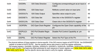
  • Please read the below register memory map again. PortA (or Port0) starts at 0x34, PortB (or Port1) starts at 0x54 and PortC (or Port2) starts at 0x74. If you want to set PortC then it starts at 0x74 for GIODIRC, not 0x54. 0x54 is for GIODIRB. In another word, you are playing with PortB rather than PortC. This is why you don't see any pins toggled for PortC. 

    This is your GIO dump aligned to 32-bit word. 

  • mmm maybe? I have two different GIO manuals I have been working with I didn't realize they have different offsets! 

    you provided one for  GIO TMS470R3x 

    and I was using GIO TMS470R1x SPNU192, I though they were the same, I see now that they are not. However how do I know which one is the same as my chip TMS470PLF111 ?  I think your manual might be more accurate?   because 0x00 GIO Global Control Register Controls the module level rest, was at 01, and I changed it to 0, and then read the GIO, which produced almost all zeros.

    00 00 00 00 00 00 00 00 00 00 00 00 00 00 00 00 00 00 00 00 00 00 00 00 00 00 00 00 00 00 00 00 00 00 00 00 00 00 00 00 00 00 00 00 00 00 00 00 00 00 00 00 00 00 00 00 00 00 00 00 00 00 00 00 00 00 00 00 00 00 00 00 00 00 00 00 00 00 00 FF 00 00 00 00 00 00 00 00 00 00 00 00 00 00 00 00 00 00 00 00 00 00 00 00 00 00 00 00 00 00 00 FF 00 00 00 00 00 00 00 00 00 00 00 00 00 00 00 00 00 00 00 00 00 00 00 00 00 00 00 00 00 00 00 FF 00 00 00 00 00 00 00 00 00 00 00 00 00 00 00 00 00 00 00 00 00 00 00 00 00 00 00 00 00 00 00 FF 00 00 00 00 00 00 00 00 00 00 00 00 00 00 00 00 00 00 00 00 00 00 00 00 00 00 00 00 00 00 00 FF 00 00 00 00 00 00 00 00 00 00 00 00 00 00 00 00 00 00 00 00 00 00 00 00 00 00 00 00 00 00 00 00 00 00 00 00 00 00 00 00 00 00 00 00 00 00 00 00 00 00 00 00 00 00 00 00 00 00 00 00 00 00 00 00 00 00 00 00 00 00 00 00 00 00 00 00 00 00 00 00 00 00 00 00 00 00 00 00 00 00 00 00 00 00 00 00 00 00 00 00 00 00 00 00 00 00 00 00 00 00 00 00 00 00 00 00 00 00 00 00 00 00 00 00 00 00 00 00 00 00 00 00 00 00 00 00 00 00 00 00 00 00 00 00 00 00 00 00 00 00 00 00 00 00 00 00 00 00 00 00 00 00 00 00 00 00 00 00 00 00 00 00 00 00 00 00 00 00 00 00 00 00 00 00 00 00 00 00 00 00 00 00 00 00 00 00 00 00 00 00 00 00 00 00 00 00 00 00 00 00 00 00 00 00 00 00 00 00 00 00 00 00 00 00 00 00 00 00 00 00 00 00 00 00 00 00 00 00 00 00 00 00 00 00 00 00 00 00 00 00 00 00 00 00 00 00 00 00 00 00 00 00 00 00 00 00 00 00 00 00 00 00 00 00 00 00 00 00 00 00 00 00 00 00 00 00 00 00 00 00 00 00 00 00 00 00 00 00 00 00 00 00 00 00

    Then flipped 0x00 back to 0x01, and it produced this:

    00 00 00 01 00 00 00 00 00 00 00 00 00 00 00 00 00 00 00 00 00 00 00 00 00 00 00 00 00 00 00 00 00 00 00 00 00 00 00 00 00 00 00 00 00 00 00 00 00 00 00 00 00 00 00 00 00 00 00 00 00 00 00 00 00 00 00 00 00 00 00 00 00 00 00 00 00 00 00 FF 00 00 00 00 00 00 00 00 00 00 00 00 00 00 00 00 00 00 00 00 00 00 00 00 00 00 00 00 00 00 00 FF 00 00 00 00 00 00 00 00 00 00 00 00 00 00 00 00 00 00 00 00 00 00 00 00 00 00 00 00 00 00 00 FF 00 00 00 00 00 00 00 00 00 00 00 00 00 00 00 00 00 00 00 00 00 00 00 00 00 00 00 00 00 00 00 FF 00 00 00 00 00 00 00 00 00 00 00 00 00 00 00 00 00 00 00 00 00 00 00 00 00 00 00 00 00 00 00 FF 00 00 00 00 00 00 00 00 00 00 00 00 00 00 00 00 00 00 00 00 00 00 00 00 00 00 00 00 00 00 00 00 00 00 00 00 00 00 00 00 00 00 00 00 00 00 00 00 00 00 00 00 00 00 00 00 00 00 00 00 00 00 00 00 00 00 00 00 00 00 00 00 00 00 00 00 00 00 00 00 00 00 00 00 00 00 00 00 00 00 00 00 00 00 00 00 00 00 00 00 00 00 00 00 00 00 00 00 00 00 00 00 00 00 00 00 00 00 00 00 00 00 00 00 00 00 00 00 00 00 00 00 00 00 00 00 00 00 00 00 00 00 00 00 00 00 00 00 00 00 00 00 00 00 00 00 00 00 00 00 00 00 00 00 00 00 00 00 00 00 00 00 00 00 00 00 00 00 00 00 00 00 00 00 00 00 00 00 00 00 00 00 00 00 00 00 00 00 00 00 00 00 00 00 00 00 00 00 00 00 00 00 00 00 00 00 00 00 00 00 00 00 00 00 00 00 00 00 00 00 00 00 00 00 00 00 00 00 00 00 00 00 00 00 00 00 00 00 00 00 00 00 00 00 00 00 00 00 00 00 00 00 00 00 00 00 00 00 00 00 00 00 00 00 00 00 00 00 00 00 00 00 00 00 00 00 00 00 00 00 00 00 00 00 00 00 00 00 00 00 00 00 00 00  

    I tried the code bellow, which .. 

     
    <Init><Address>0xFFF7BC74</Address><Value>0x00000FF</Value><Bytes>8</Bytes></Init>
    <Init><Address>0xFFF7BC84</Address><Value>0x00000FF</Value><Bytes>8</Bytes></Init>
    <Init><Address>0xFFF7BC80</Address><Value>0x0000010</Value><Bytes>8</Bytes></Init>
    <Init><Address>0xFFF7BC84</Address><Value>0x0000010</Value><Bytes>8</Bytes></Init>
    <Init><Address>0xFFF7BC80</Address><Value>0x00000FF</Value><Bytes>8</Bytes></Init>
    <Init><Address>0xFFF7BC84</Address><Value>0x0000055</Value><Bytes>8</Bytes></Init>
    <Init><Address>0xFFF7BC7C</Address><Value>0x0000055</Value><Bytes>8</Bytes></Init>

    produced GIO dump:

    00 00 00 01 00 00 00 00 00 00 00 00 00 00 20 00 00 00 00 00 00 00 00 00 00 00 20 00 00 00 20 00 00 80 20 00 00 00 00 00 00 00 00 00 00 00 00 00 00 00 00 00 00 00 00 00 00 00 00 FF 00 00 00 00 00 00 00 00 00 00 00 00 00 00 00 00 00 00 00 FF 00 00 00 FF 00 00 00 00 00 00 00 F7 00 00 00 00 00 00 00 00 00 00 00 00 00 00 00 00 00 00 00 FF 00 00 00 F7 00 00 00 FF 00 00 00 55 00 00 00 55 00 00 00 55 00 00 00 55 00 00 00 00 00 00 00 FF 00 00 00 FF 00 00 00 00 00 00 00 C2 00 00 00 00 00 00 00 00 00 00 00 00 00 00 00 00 00 00 00 FD 00 00 00 D4 00 00 00 00 00 00 00 00 00 00 00 00 00 00 00 00 00 00 00 00 00 00 00 00 00 00 00 FF 00 00 00 03 00 00 00 00 00 00 00 00 00 00 00 00 00 00 00 00 00 00 00 00 00 00 00 00 00 00 00 00 00 00 00 00 00 00 00 00 00 00 00 00 00 00 00 00 00 00 00 00 00 00 00 00 00 00 00 00 00 00 00 00 00 00 00 00 00 00 00 00 00 00 00 00 00 00 00 00 00 00 00 00 00 00 00 00 00 00 00 00 00 00 00 00 00 00 00 00 00 00 00 00 00 00 00 00 00 00 00 00 00 00 00 00 00 00 00 00 00 00 00 00 00 00 00 00 00 00 00 00 00 00 00 00 00 00 00 00 00 00 00 00 00 00 00 00 00 00 00 00 00 00 00 00 00 00 00 00 00 00 00 00 00 00 00 00 00 00 00 00 00 00 00 00 00 00 00 00 00 00 00 00 00 00 00 00 00 00 00 00 00 00 00 00 00 00 00 00 00 00 00 00 00 00 00 00 00 00 00 00 00 00 00 00 00 00 00 00 00 00 00 00 00 00 00 00 00 00 00 00 00 00 00 00 00 00 00 00 00 00 00 00 00 00 00 00 00 00 00 00 00 00 00 00 00 00 00 00 00 00 00 00 00 00 00 00 00 00 00 00 00 00 00 00 00 00 00 00 00 00 00 00 00 00 00 00 00 00 00 00 00 00 00 00 00 00 00 00 00 00 00 00

  • you provided one for  GIO TMS470R3x

    The one I provided is the correct description for GIO.  I find another device of the same generation with the same platform architecture. Here is the TRM. I can't find the same TRM document for TMS470PLF11. It is EOL'ed as I mentioned multiple times. I have no history of it. This attached TRM will be pretty much the same for all the module description. It is possible that a particular module that is available in TMS470PLF11 is not available in this TRM. Conversely, it is also possible a module that is described in this TRM is not available in TMS470PLF11. 

    spnu239b.pdf

    produced GIO dump:

    00 00 00 01 00 00 00 00 00 00 00 00 00 00 20 00 00 00 00 00 00 00 00 00 00 00 20 00 00 00 20 00 00 80 20 00 00 00 00 00 00 00 00 00 00 00 00 00 00 00 00 00 00 00 00 00 00 00 00 FF 00 00 00 00 00 00 00 00 00 00 00 00 00 00 00 00 00 00 00 FF 00 00 00 FF 00 00 00 00 00 00 00 F7 00 00 00 00 00 00 00 00 00 00 00 00 00 00 00 00 00 00 00 FF 00 00 00 F7 00 00 00 FF 00 00 00 55 00 00 00 55 00 00 00 55 00 00 00 55 00 00 00 00 00 00 00 FF 00 00 00 FF 00 00 00 00 00 00 00 C2 00 00 00 00 00 00 00 00 00 00 00 00 00 00 00 00 00 00 00 FD 00 00 00 D4 00 00 00 00 00 00 00 00 00 00 00 00 00 00 00 00 00 00 00 00 00 00 00 00 00 00 00 FF 00 00 00 03 00 00 00 00 00 00 00 00 00 00 00 00 00 00 00 00 00 00 00 00 00 00 00 00 00 00 00 00 00 00 00 00 00 00 00 00 00 00 00 00 00 00 00 00 00 00 00 00 00 00 00 00 00 00 00 00 00 00 00 00 00 00 00 00 00 00 00 00 00 00 00 00 00 00 00 00 00 00 00 00 00 00 00 00 00 00 00 00 00 00 00 00 00 00 00 00 00 00 00 00 00 00 00 00 00 00 00 00 00 00 00 00 00 00 00 00 00 00 00 00 00 00 00 00 00 00 00 00 00 00 00 00 00 00 00 00 00 00 00 00 00 00 00 00 00 00 00 00 00 00 00 00 00 00 00 00 00 00 00 00 00 00 00 00 00 00 00 00 00 00 00 00 00 00 00 00 00 00 00 00 00 00 00 00 00 00 00 00 00 00 00 00 00 00 00 00 00 00 00 00 00 00 00 00 00 00 00 00 00 00 00 00 00 00 00 00 00 00 00 00 00 00 00 00 00 00 00 00 00 00 00 00 00 00 00 00 00 00 00 00 00 00 00 00 00 00 00 00 00 00 00 00 00 00 00 00 00 00 00 00 00 00 00 00 00 00 00 00 00 00 00 00 00 00 00 00 00 00 00 00 00 00 00 00 00 00 00 00 00 00 00 00 00 00 00 00 00 00 00 00

    You GIO dumps show the correct output. Look at 0xFFF7BC78 which the GIODINC data input register, it shows 0x55 which should be the end result after you try the experiment. 

  • I’m trying to toggle HET now do you have a manual and examples for HET output using het , as io.

    also I tried to do a loop with 255 or 0xff iterations and the code crashes. Do I need to feed to watch dog every iteration?

  • I have attempted, to write to the HET output pins but it isn't working 

    my het offset plus:

    0x38  = 0x04878196 //data in

    0x3C = 0x840194 //HET out

    0x40 = 0x840194 //HET SET

    0x44 = 0x840194 //HET CLR

    And this is the dump after the write which I have in a loop of 255 iterations. Which isn't crashing now that I am writing the watch dog. 

    00 01 00 03 00 00 05 00 00 00 00 00 00 00 00 00 00 00 00 00 00 00 00 00 00 00 00 00 FF FF FF FF 00 00 00 00 00 00 00 00 00 00 00 00 00 00 00 00 00 00 00 00 01 8C 3D FC 04 87 81 16 00 84 01 14 00 84 01 14 00 84 01 14 00 00 00 00 EF FF FF FF 06 13 80 03 00 00 00 00 00 00 00 00 00 00 00 00 00 00 00 00 00 00 00 00 00 00 00 00 00 00 00 00 00 00 00 00 00 00 00 00 00 00 00 00 00 00 00 00 00 00 00 00 00 00 00 00 00 00 00 00 00 00 00 00 00 00 00 00 00 00 00 00 00 00 00 00 00 00 00 00 00 00 00 00 00 00 00 00 00 00 00 00 00 00 00 00 00 00 00 00 00 00 00 00 00 00 00 00 00 00 00 00 00 00 00 00 00 00 00 00 00 00 00 00 00 00 00 00 00 00 00 00 00 00 00 00 00 00 00 00 00 00 00 00 00 00 00 00 00 00 00 00 00 00 00 00 00 00 00 00 00 00 00 00 00 00 00 00 00 00 00 00 00 00 00 00

  • I have attempted, to write to the HET output pins but it isn't working 

    my het offset plus:

    0x38  = 0x04878196 //data in

    0x3C = 0x840194 //HET out

    0x40 = 0x840194 //HET SET

    0x44 = 0x840194 //HET CLR

    Did you configure HETDIR register at 0x34? 

    Your dump shows the HETDIR register at 0x34 is 0x188C3DFC. This means not all pins are configured as output. You need to write 0xFFFFFFFF to HETDIR register if you want to test out HET pins for output pins. Bear in mind that for the pins that are not configured as outputs in HETDIR, writing to the corresponding HETDOUT, HETSET, HETCLR will have no effect. 

  • ok thanks will I will try that, I see some of the pins that I actually want are on the SPI peripherals. Sorry to ask again but do you have a  MibSPI manual for the closest chip that  I have? MIB offset plus 0x3C is being written to toggle pins in my code, but in the manual I have it says that is reserved?  

  • but do you have a  MibSPI manual for the closest chip that  I have?

    I thought I gave you the below TRM in my last reply. This TRM is for TMS470PVF24xB device which shares the same architecture as your device. The MibSPI chapter should be the same between the two devices. 

    spnu239b.pdf

    MIB offset plus 0x3C is being written to toggle pins in my code, but in the manual I have it says that is reserved? 

    Which document are you referring to?

    In the TRM I attached, MibSPI + 0x3C is the SPIDAT1 register. First, this is not reserved. Second, this is the data register for SPI functional mode. This register is not used for GIO. 

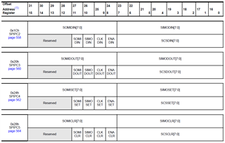
    In order to use MibSPI pins for GIO, you need to configure registers SPIPC0, SPIPC1, SPIPC2, SPIPC3, SPIPC4 and SPIPC5 registers.

    1. Program SPIPC0 to use MibSPI pins for GIO pins. By default after reset, it is already in GIO mode. 

    2. Program SPIPC1 to use MibSPI pins as either input or output pins. If you want to use MibSPI pins for GIO output pins, you need to write 1 to the corresponding pins. 

    3. Program either  SPIPC3 (DOUT), SPIPC4 (SET) and SPIPC5 (CLR) to set or clear the pins like the way you did for GIO module. 

    4. Read SPIPC2 (DIN) register for the state of the pins. 

    Please go through the TRM for details. 

  • assume you rock! Sorry I didn't realize that the mibspi manual was within the TRM.  Is is possible to latch these pins on? I am getting the pin only staying on for 3-4 seconds or so. 

  • Is is possible to latch these pins on? I am getting the pin only staying on for 3-4 seconds or so. 

    I'm not clear what you mean as to latch these pins on. If you set a pin high, the pin is supposed to stay high indefinitely.  The DOUT register is a storage element, more or less like a latch. Once you set the DOUT register to certain state, it will stay in that state until you change it. I don't know why you said they only stay for 3-4 seconds. Check your program and read what is the value of DOUT register. Your pin should reflect what the DOUT register unless you have some type of drive conflict on the board. That will be a board level hardware issue.

  • They issue is it’s never written to the Dout, the existing codes only writing to Ox3C after init. And the isn’t much documentation for that offset bits 16-23 CNSR no idea what they do 

  • They issue is it’s never written to the Dout, the existing codes only writing to Ox3C after init. And the isn’t much documentation for that offset bits 16-23 CNSR no idea what they do 

    CSNR field is described in TRM. However, I have no way to know what the prior author of your code was intending to do with writing to 0x3C after init. If you want to use MibSPI pins for GPIO, you will need to follow the instructions I provided in my last reply. All I can say is that the SPIDAT1 register at 0x3C is intended for MibSPI functional operation. You write to the TXDATA[15:0] to cause the data to shift out of the MOSI pin. CSNR field is to specify which chip select is active for the transfer. 

  • You are very helpful, couldn't do this wihtout you! Ok yes but chip select of what exactly? That has nothing to do with witch pin output does it? 

    Could the 0x3C be some sort of testing procedure for certain pins? This function is called using a tester to momentarily turn on the pins. And I traced one of the pins back to a GIO pin as well.

    Can you use mibspi to test pins other modules like GIO internally? Or maybe the pins on the board are tied to two pins gio, and mibspi?   

  • Ok yes but chip select of what exactly?

    This is a MibSPI device with the capability to connect to multiple slave devices. Each slave device will be selected by an individual CS signal. You write to CSNR field to specify which slave device you want to transmit the data to. The CSNR field and as matter of fact the entire SPIDAT1 register has nothing to do with GIO operation. You will need to consult with the prior author on what slave device is intended for communication. BTW, how do you know the code is only writing to CSNR field, and not the entire register?

    Could the 0x3C be some sort of testing procedure for certain pins? This function is called using a tester to momentarily turn on the pins. And I traced one of the pins back to a GIO pin as well.

    Again, that is your application. I wouldn't know. Perhaps, after init, your application was trying to send some test data or real data to slave to establish a communication. I have seen many applications that will send data to other devices via CAN, SPI, UART etc. 

    Can you use mibspi to test pins other modules like GIO internally? Or maybe the pins on the board are tied to two pins gio, and mibspi? 

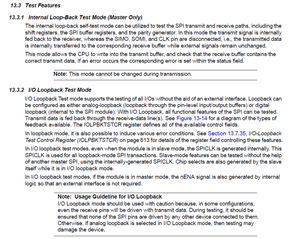
    You need to check if the code was doing some type of loopback selftest. Check your code if it is reading data from SPIBUF at 0x40. If you see this, you may be in some loopback mode. Read the below section if your code is doing test mode. 

  • The existing code is writing 32 bits to 0x3c

    0x3c = 0x000y00xx , were xx is the pin to test? And y = CNSR which is 6 or 5. Or turn on  , should be 8 available pins. Seems it only uses 7, and I can individually toggle the 7 pins on. They are tested with my multi meter. However they only stay on for a very short period of time. sending   0x100600FF turns on all 7 pins. 

    This is the existing code. 

    SPI_Base_plus_offset_0x3C = 0x000y00xx; //example 0x000600FF or 0x000500FF
    count = 32;
    do {
    count = count + -1;
    if (count == 0) break;
    } while ((SPI_Base_plus_offset_0x12._0_1 & 1) == 0);
    return SPI_Base_plus_offset_0x40 & 0xff;

    No idea what it is doing checking for offset 0x12._0_1 and with 1, nor do I know what ._01 means in C it is maybe a half byte location or bit number of offset 0x12? 

    Then even more puzzling is why it returns  offset 0x40 and with 0xff? You asked about offset 0x40 if it was being read? It is being read in another function. 

    I have tried modifying the function to remove the 0x12, and or 0x40 steps and only write 0x3C, but that doesn't turn on the pins momentarily. I also tired skipping this function and just directly writing 0x3C, but that also never toggles any pin on. 

    I don't see any documentation explaining what each bit represents for CNSR, it's only 5 or 6 so  0101 or 0110. When I set CNSR to 5 the pins don't toggle on? perhaps this toggles them off? 

    I don't see anything in the documentation about monitoring 0x12, offset 0x12 isn't even listed. And 0x40 is supposed to be read only not able to write to it correct?  

  • 0x3c = 0x000y00xx , were xx is the pin to test?

    No, xx is not the pin to test. xx is just is the data to send through SPI MOSI pin. Your prior colleague wants to send out 0xFF as the data on MOSI pin and coded as such. 0xFF does NOT mean to set all 8 pins high. 

    No idea what it is doing checking for offset 0x12._0_1 and with 1, nor do I know what ._01 means in C it is maybe a half byte location or bit number of offset 0x12? 

    You need to contact your colleague what he/she really meant to be. It seems to me SPI_Base_plus_offset_0x12 is some type of structure as he is referring to a member of the structure as ._0_1. You need to read the code to understand where SPI_Base_plus_offset_0x12 is defined.   This is more general C questions rather than MCU or SPI question. 

    Then even more puzzling is why it returns  offset 0x40 and with 0xff?

    He is reading the SPIBUF register and masking the lower 8 bits, that's it. 

    I have tried modifying the function to remove the 0x12, and or 0x40 steps and only write 0x3C, but that doesn't turn on the pins momentarily.

    As I mentioned in the prior replied, you need to configure these SPI pins for GIO mode first, using SPIPC0 register at 0x14. Change these pins to output pins in SPIPC1 register at 0x18 before you can set/clear these pins using SPIPC3, SPIPC4, and SPIPC5 registers. 

    I don't see any documentation explaining what each bit represents for CNSR, it's only 5 or 6 so  0101 or 0110. When I set CNSR to 5 the pins don't toggle on? perhaps this toggles them off? 

    You really need to read the TRM, please. 

    13.2.9 Decoded and Encoded Chip Select (Master Only)
    The SPI can connect to up to 8 individual slave devices using decoded chip-selects by routing one wire to
    each slave. For the decoded mode, the 8 chip selects in the control field are directly connected to the 8 pins.
    The default value of each chip select, i.e., not active, can be configured via the register CSDEF. During a
    transmission, the value of the chip select control field (CSNR[7:0]) of the SPIDAT1 register (SPIDAT1[23:16])
    is driven on the SPISCS [7:0] pins (if available). When the transmission finishes the default chip-select value
    (defined by the CSDEF register) is put on the SPISCS [7:0] pins.
    The SPI can support more than 8 slaves by using encoded chip selects. To connect the SPI with encoded
    slaves devices, the CSNR field allows multiple active SPISCS pins at the same time, which enables binary
    encoded chip selects from 0 to 255. To use encoded chip selects, all eight chip select lines have to be
    connected to each slave device and each slave needs to have a unique chip-select address. The CSDEF
    register is used to provide the address at which slaves devices are all de-selected.
    Users can combine decoded and encoded chip selects. For example, n SPISCS pins can be used for
    encoding a n-bit address and the remaining pins can be connected to decoded-mode slaves.