Part Number: TMS570LC4357
Other Parts Discussed in Thread: HALCOGEN
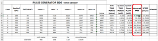
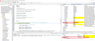
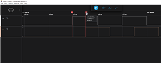
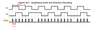
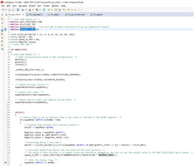
sir now i need to find speed , in quadrature pulse generator providing input to pin epeqA and epeqB , how to find speed what will be configuration should be in halcoGen , input is tiime period 20millisecond , frequency is 50 hz , i attach my code , for that what configuration we should , will u help me
#include "HL_sys_common.h"
/* USER CODE BEGIN (1) */
#include "HL_sys_core.h"
#include "math.h"
#include "HL_sci.h"
#include "HL_eqep.h"
#define UART sciREG1
#define clkfreq 75000000
#define PPR 30U
uint16 data_buffer[10];
void sciDisplayText(sciBASE_t *sci, uint16 *text, uint32 length);
uint16 eqepReadCapturePeriodLatch (eqepBASE_t *eqep);
uint32_t posCountValBef;
uint32_t posCountValAft ;
uint16 deltaT = 0U;
uint8 pi = 3;
uint8 D = 1 ;
uint8 circumference ;
uint8 velocity = 0;
uint16 frequency ;
uint16 RPM= 0;
uint16 Distance = 0;
uint16 speed = 0;
uint16 period ;
uint8 direction;
uint16 status;
uint16 time_period ;
void wait(uint32 time);
#define INDEX 10
/* USER CODE END */
/** @fn void main(void)
* @brief Application main function
* @note This function is empty by default.
*
* This function is called after startup.
* The user can use this function to implement the application.
*/
/* USER CODE BEGIN (2) */
/* USER CODE END */
int main(void)
{
/* USER CODE BEGIN (3) */
QEPInit();
sciInit();
_enable_interrupt_();
/* Enable Position Counter */
eqepEnableCounter(eqepREG2);
/* Enable Unit Timer. */
eqepEnableUnitTimer(eqepREG2);
/* Enable capture timer and capture period latch. */
eqepEnableCapture(eqepREG2);
/* Read the position counter value before the index event */
posCountValBef = (uint16)eqepReadPosnCompare(eqepREG2);
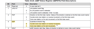
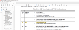
/* Status flag is set to indicate that a new value is latched in the QCPRD register. */
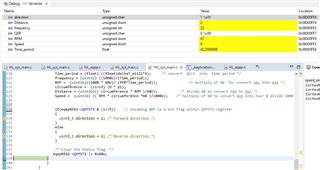
if((eqepREG2->QEPSTS & 0x80U) != 0U)
{
period = eqepREG2->QCPRDLAT;
deltaT = eqepREG2->QCPRD;
posCountValAft = (uint16)eqepReadStatus(eqepREG2);
velocity = (PPR / deltaT);
/* Assign value in period register into period variable */
circumference = (double) (D * pi); /* cirumference of wheel ,convert Diameter into meter then used */
frequency = (uint16)((1000000U)/(uint16)(time_period)); /* to convert microsec to sec */
RPM = (uint16)((frequency * 60)/ PPR); /* multiply of 60 for convert sec into min */
Distance = (uint16)(( circumference * RPM )/60); /* divide 60 to convert Min to Sec */
speed = (uint16) (( RPM * circumference *60 )/1000); /* Multiply of 60 to convert min into hour & divide 1000 for m into Km */
/* Read the position counter value after the index event */
if (posCountValAft > posCountValBef) {
direction = 1; /* Direction is farward */
} else {
direction = 2; /* Direction is backward */
}
/* Clear the Status flag. */
eqepREG2->QEPSTS |= 0x80U;
}
thank you
jeeva


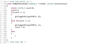

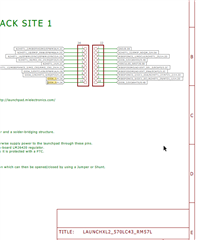
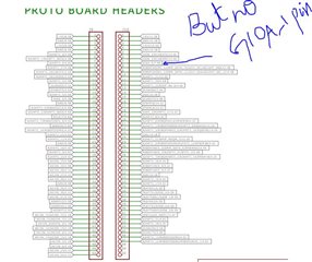 i have attached schematic of controller which one iam using . instead of that iam trying to use pin 36 gioA_2 bt no use