This thread has been locked.
If you have a related question, please click the "Ask a related question" button in the top right corner. The newly created question will be automatically linked to this question.
Hi,
this is my first time working with Sitara and posting a question here, so please bear with me if the question seems somewhat unusual :)
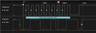
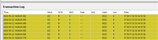
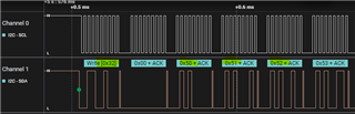
I have occasional I2C bus hanging due to arbitration loss after an "ungraceful" reset. How can I address this?
Before initiating any I2C communication, I call the Cdd_I2c_Init function. However, due to the design, it's impossible to call Cdd_I2c_DeInit before a "warm-start" reset.
I'm using the MCAL Version AM263x 08.06.02, and I'm utilizing the Cdd_I2c Driver included in that package.
As a workaround, I modified the startup sequence to run Cdd_I2c_Init, Cdd_I2c_DeInit, and then Cdd_I2c_Init again to reset the I2C peripheral. This approach has somewhat helped, but I'm still facing issues with the bus hanging. To address the remaining hanging issues, I set the CddI2cArbitrationLossParam variable to CDD_I2C_RECURRENT_MODE, aiming to send 9 clock pulses to the slave to synchronize the bus - but this hasn't been effective.
Of course, there might be issues with the target I'm communicating with, but do you have any suggestions on what I can do from the microcontroller side to resolve the I2C bus hanging, despite resetting the I2C peripheral and using CDD_I2C_RECURRENT_MODE?
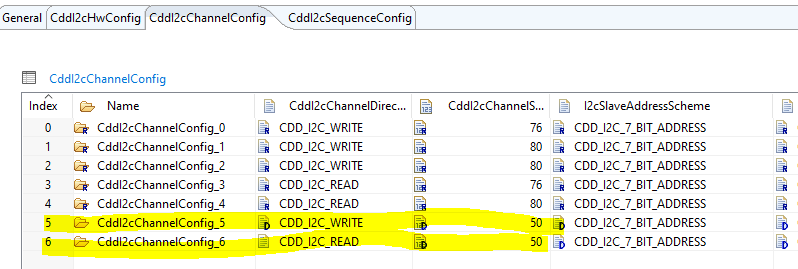
Additionally, I'm using the I2C1 instance in polling mode and running the communication at a 100KHz bitrate.
Moreover, in Code Composer, I see the hang in Cdd_I2c_Polling_Mode_Receive, specifically in the while loop on line 509. The IsrStatus variable holds the value 400h.
Any suggestions for improving the implementation are most welcome.
Many thanks,
Mikael
Hi Mikael,
The AM263x Control Card uses I2C0 and I2C2 ports as controller for EEPROM, Temperature sensor, LED driver etc. The MCAL includes an I2C example of reading/writing data to an on-board EEPROM. The example is located in .\mcal\examples\I2c
How did you generate MCAL I2C configuration file?
Hi, I'm using I2C1 primarily to read the date and time from an RTC, with occasional writes to update the RTC. I'd like to mention that reading from the bus usually works well. I'm aware of the examples in the folder you mentioned and have implemented the read and write operations similarly.
The configuration is essentially a two-parter: i) it is adapted from examples_config\I2c_Demo_Cfg\ to fit my needs, and ii) I have also configured the I2C1 instance in the .syscfg. Perhaps these two configurations are conflicting or overwriting each other. Do you think that's the case? I've tried removing the configuration in the .syscfg, but I still encounter the same issue.
Hi Mike,
Do you add a sequence and a channel for writing data to RTC using I2C1 (HW_UNIT_1)? For example channel 5 and channel 6 in my EB config:
Did you enable the interrupt for I2C1? The MCAL driver doesn't have function to enable/disable module's interrupt.
In my Cdd_I2c_Cfg.c file, I have a similar configuration to yours. However, I'm only using CDD_I2C_HW_UNIT 1, not 0 or 2, configured for channels 0 and 1.
Also, I didn't enable interrupts for the I2C1 instance - it's running entirely in polling mode.
Hi Mikael,
I am sorry for late response. I did a test this morning using MCAL driver. I sent message to I2C slave (aardvark), but I didn't see the data on I2C1 bus. I am investigating if I2C1 is supported in the MCAL driver.
No worries about the late reply. Thank you for further testing and investigating the issue.
Hi Mikael,
The I2C1 of MCAL driver works. I configured I2C to write data without slave attached, and probed the SCL/SDA pins on AM263x CC dock card. I got the correct clock signal, and data signal: slave address is 0x32, write mode.
attached are the MCAL I2C and Port configuration file generated by EB Tresos:
/* ====================================================================== * Copyright (c) 2022-2023 Texas Instruments Incorporated * * All rights reserved. Property of Texas Instruments Incorporated. * Restricted rights to use, duplicate or disclose this code are * granted through contract. * * The program may not be used without the written permission * of Texas Instruments Incorporated or against the terms and conditions * stipulated in the agreement under which this program has been * supplied. * ==================================================================== */ /** * \file Port_PBcfg.c * * \brief This file contains generated post build configuration file * for PORT MCAL driver * */ /********************************************************************************************************************** Project: AM263x_MCAL_Configuation Date : 2024-05-22 11:26:10 This file is generated by EB Tresos Do not modify this file, otherwise the software may behave in unexpected way. *********************************************************************************************************************/ #define PORT_CFG_SOURCE /********************************************************************************************************************** * INCLUDES *********************************************************************************************************************/ #include "Std_Types.h" #include "Port.h" #include "hw_ctrl_core.h" /********************************************************************************************************************** * VERSION CHECK *********************************************************************************************************************/ /* Version checking */ #if ((PORT_SW_MAJOR_VERSION != (9U))||(PORT_SW_MINOR_VERSION != (0U))) #error "Version numbers of Port_PBcfg.c and Port.h are inconsistent!" #endif #if ((PORT_CFG_MAJOR_VERSION != (9U))||(PORT_CFG_MINOR_VERSION != (0U))) #error "Version numbers of Port_PBcfg.c and Port_Cfg.h are inconsistent!" #endif /********************************************************************************************************************** * LOCAL MACROS **********************************************************************************************************************/ /*MCAL: S MR:1.1 <APPROVED> "Reason - Start Section Code is also defined Port.h" */ #define PORT_START_SEC_CONFIG_DATA /*MCAL: S MR:19.1 <APPROVED> "Reason - This is the format for specifying memory sections" */ #include "Port_MemMap.h" /*<PORT_PIN_CONFIGURATION>*/ static CONST( Port_PinConfigType, PORT_PBCFG) PortConfigSet_0_PinConfig[] = { { .Port_PinId = 80, .Port_PullInhibitEnable = PORT_PIN_PULL_INHIBIT_DISABLE, .Port_OutputOverride_Ctrl = PORT_PIN_OUTPUT_RETAIN_HW_CTRL, .Port_InputOverride_Ctrl = PORT_PIN_INPUT_RETAIN_HW_CTRL, .Port_DirectionChangeable = FALSE, .Port_PinModeChangeable = FALSE, .Port_PinLevelValue = PORT_PIN_LEVEL_LOW, .Port_PinDirection = PORT_PIN_IN, .Port_PinInitialMode = PORT_PIN_MODE_GPIOCD, .Port_PullTypeSelect = PORT_PIN_PULLTYPE_PULLDOWN, .Port_PinHSmasterEnable = FALSE, .Port_PinHSmodeEnable = FALSE, .Port_InversionSelect = PORT_NONINV, .Port_QualifierTypeSelect = PORT_QUALTYPE_DEFAULT, .Port_SlewControl = PORT_PIN_SLEWCONTROL_SLOW_SLEW, .Port_NumPortModes = 1, .Port_PinMode = { [0] = { .mode = PORT_PIN_MODE_GPIOCD, .muxmode = 7, }, }, .Port_PinDioRegId = (2 - 1U), /* GPIO register index is 0 based */ .Port_PinDioChannelId = 29, .Port_RegOffsetAddr = PING1_EPWM9_A, .Port_PinSignalName = (const sint8 *)"GPIOCD_61", .Port_PinName = (const sint8 *)"PIN_G1", .Port_PinSetEdgeTrigger = FALSE, .Port_PinSelectEdgeTrigger = PORT_RISING_EDGE, }, { .Port_PinId = 96, .Port_PullInhibitEnable = PORT_PIN_PULL_INHIBIT_DISABLE, .Port_OutputOverride_Ctrl = PORT_PIN_OUTPUT_RETAIN_HW_CTRL, .Port_InputOverride_Ctrl = PORT_PIN_INPUT_RETAIN_HW_CTRL, .Port_DirectionChangeable = FALSE, .Port_PinModeChangeable = FALSE, .Port_PinLevelValue = PORT_PIN_LEVEL_LOW, .Port_PinDirection = PORT_PIN_IN, .Port_PinInitialMode = PORT_PIN_MODE_GPIOCD, .Port_PullTypeSelect = PORT_PIN_PULLTYPE_PULLDOWN, .Port_PinHSmasterEnable = FALSE, .Port_PinHSmodeEnable = FALSE, .Port_InversionSelect = PORT_NONINV, .Port_QualifierTypeSelect = PORT_QUALTYPE_DEFAULT, .Port_SlewControl = PORT_PIN_SLEWCONTROL_SLOW_SLEW, .Port_NumPortModes = 1, .Port_PinMode = { [0] = { .mode = PORT_PIN_MODE_GPIOCD, .muxmode = 7, }, }, .Port_PinDioRegId = (2 - 1U), /* GPIO register index is 0 based */ .Port_PinDioChannelId = 30, .Port_RegOffsetAddr = PINJ2_EPWM9_B, .Port_PinSignalName = (const sint8 *)"GPIOCD_62", .Port_PinName = (const sint8 *)"PIN_J2", .Port_PinSetEdgeTrigger = FALSE, .Port_PinSelectEdgeTrigger = PORT_RISING_EDGE, }, { .Port_PinId = 69, .Port_PullInhibitEnable = PORT_PIN_PULL_INHIBIT_DISABLE, .Port_OutputOverride_Ctrl = PORT_PIN_OUTPUT_RETAIN_HW_CTRL, .Port_InputOverride_Ctrl = PORT_PIN_INPUT_RETAIN_HW_CTRL, .Port_DirectionChangeable = FALSE, .Port_PinModeChangeable = FALSE, .Port_PinLevelValue = PORT_PIN_LEVEL_LOW, .Port_PinDirection = PORT_PIN_IN, .Port_PinInitialMode = PORT_PIN_MODE_GPIOCD, .Port_PullTypeSelect = PORT_PIN_PULLTYPE_PULLDOWN, .Port_PinHSmasterEnable = FALSE, .Port_PinHSmodeEnable = FALSE, .Port_InversionSelect = PORT_NONINV, .Port_QualifierTypeSelect = PORT_QUALTYPE_DEFAULT, .Port_SlewControl = PORT_PIN_SLEWCONTROL_SLOW_SLEW, .Port_NumPortModes = 1, .Port_PinMode = { [0] = { .mode = PORT_PIN_MODE_GPIOEF, .muxmode = 7, }, }, .Port_PinDioRegId = (3 - 1U), /* GPIO register index is 0 based */ .Port_PinDioChannelId = 5, .Port_RegOffsetAddr = PINE2_EPWM3_A, .Port_PinSignalName = (const sint8 *)"GPIOEF_69", .Port_PinName = (const sint8 *)"PIN_K4", .Port_PinSetEdgeTrigger = FALSE, .Port_PinSelectEdgeTrigger = PORT_RISING_EDGE, }, { .Port_PinId = 21, .Port_PullInhibitEnable = PORT_PIN_PULL_INHIBIT_DISABLE, .Port_OutputOverride_Ctrl = PORT_PIN_OUTPUT_RETAIN_HW_CTRL, .Port_InputOverride_Ctrl = PORT_PIN_INPUT_RETAIN_HW_CTRL, .Port_DirectionChangeable = FALSE, .Port_PinModeChangeable = FALSE, .Port_PinLevelValue = PORT_PIN_LEVEL_LOW, .Port_PinDirection = PORT_PIN_IN, .Port_PinInitialMode = PORT_PIN_MODE_GPIOI, .Port_PullTypeSelect = PORT_PIN_PULLTYPE_PULLDOWN, .Port_PinHSmasterEnable = FALSE, .Port_PinHSmodeEnable = FALSE, .Port_InversionSelect = PORT_INVTYPE_DEFAULT, .Port_QualifierTypeSelect = PORT_QUALTYPE_DEFAULT, .Port_SlewControl = PORT_PIN_SLEWCONTROL_SLOW_SLEW, .Port_NumPortModes = 1, .Port_PinMode = { [0] = { .mode = PORT_PIN_MODE_GPIOI, .muxmode = 7, }, }, .Port_PinDioRegId = (5 - 1U), /* GPIO register index is 0 based */ .Port_PinDioChannelId = 6, .Port_RegOffsetAddr = PINB13_I2C0_SDA, .Port_PinSignalName = (const sint8 *)"GPIOI_134", .Port_PinName = (const sint8 *)"PIN_B13", .Port_PinSetEdgeTrigger = FALSE, .Port_PinSelectEdgeTrigger = BOTH_EDGE, }, { .Port_PinId = 49, .Port_PullInhibitEnable = PORT_PIN_PULL_INHIBIT_DISABLE, .Port_OutputOverride_Ctrl = PORT_PIN_OUTPUT_RETAIN_HW_CTRL, .Port_InputOverride_Ctrl = PORT_PIN_INPUT_RETAIN_HW_CTRL, .Port_DirectionChangeable = FALSE, .Port_PinModeChangeable = FALSE, .Port_PinLevelValue = PORT_PIN_LEVEL_HIGH, .Port_PinDirection = PORT_PIN_DEFAULT, .Port_PinInitialMode = PORT_PIN_MODE_I2C2, .Port_PullTypeSelect = PORT_PIN_PULLTYPE_PULLDOWN, .Port_PinHSmasterEnable = FALSE, .Port_PinHSmodeEnable = FALSE, .Port_InversionSelect = PORT_INVTYPE_DEFAULT, .Port_QualifierTypeSelect = PORT_QUALTYPE_DEFAULT, .Port_SlewControl = PORT_PIN_SLEWCONTROL_SLOW_SLEW, .Port_NumPortModes = 1, .Port_PinMode = { [0] = { .mode = PORT_PIN_MODE_I2C2, .muxmode = 1, }, }, .Port_PinDioRegId = PORT_DIO_INVALID_REG_ID, /* GPIO register index is 0 based */ .Port_PinDioChannelId = PORT_DIO_INVALID_REG_ID, .Port_RegOffsetAddr = PINC7_UART0_RTSN, .Port_PinSignalName = (const sint8 *)"I2C2_SCL", .Port_PinName = (const sint8 *)"PIN_C7", .Port_PinSetEdgeTrigger = FALSE, .Port_PinSelectEdgeTrigger = PORT_RISING_EDGE, }, { .Port_PinId = 32, .Port_PullInhibitEnable = PORT_PIN_PULL_INHIBIT_DISABLE, .Port_OutputOverride_Ctrl = PORT_PIN_OUTPUT_RETAIN_HW_CTRL, .Port_InputOverride_Ctrl = PORT_PIN_INPUT_RETAIN_HW_CTRL, .Port_DirectionChangeable = FALSE, .Port_PinModeChangeable = FALSE, .Port_PinLevelValue = PORT_PIN_LEVEL_HIGH, .Port_PinDirection = PORT_PIN_DEFAULT, .Port_PinInitialMode = PORT_PIN_MODE_I2C2, .Port_PullTypeSelect = PORT_PIN_PULLTYPE_PULLDOWN, .Port_PinHSmasterEnable = FALSE, .Port_PinHSmodeEnable = FALSE, .Port_InversionSelect = PORT_INVTYPE_DEFAULT, .Port_QualifierTypeSelect = PORT_QUALTYPE_DEFAULT, .Port_SlewControl = PORT_PIN_SLEWCONTROL_SLOW_SLEW, .Port_NumPortModes = 1, .Port_PinMode = { [0] = { .mode = PORT_PIN_MODE_I2C2, .muxmode = 1, }, }, .Port_PinDioRegId = PORT_DIO_INVALID_REG_ID, /* GPIO register index is 0 based */ .Port_PinDioChannelId = PORT_DIO_INVALID_REG_ID, .Port_RegOffsetAddr = PINB7_UART0_CTSn, .Port_PinSignalName = (const sint8 *)"I2C2_SDA", .Port_PinName = (const sint8 *)"PIN_B7", .Port_PinSetEdgeTrigger = FALSE, .Port_PinSelectEdgeTrigger = PORT_RISING_EDGE, }, { .Port_PinId = 2, .Port_PullInhibitEnable = PORT_PIN_PULL_INHIBIT_ENABLE, .Port_OutputOverride_Ctrl = PORT_PIN_OUTPUT_RETAIN_HW_CTRL, .Port_InputOverride_Ctrl = PORT_PIN_INPUT_RETAIN_HW_CTRL, .Port_DirectionChangeable = FALSE, .Port_PinModeChangeable = FALSE, .Port_PinLevelValue = PORT_PIN_LEVEL_HIGH, .Port_PinDirection = PORT_PIN_DEFAULT, .Port_PinInitialMode = PORT_PIN_MODE_SPI0, .Port_PullTypeSelect = PORT_PIN_PULLTYPE_PULLDOWN, .Port_PinHSmasterEnable = FALSE, .Port_PinHSmodeEnable = FALSE, .Port_InversionSelect = PORT_INVTYPE_DEFAULT, .Port_QualifierTypeSelect = PORT_QUALTYPE_DEFAULT, .Port_SlewControl = PORT_PIN_SLEWCONTROL_SLOW_SLEW, .Port_NumPortModes = 1, .Port_PinMode = { [0] = { .mode = PORT_PIN_MODE_SPI0, .muxmode = 0, }, }, .Port_PinDioRegId = PORT_DIO_INVALID_REG_ID, /* GPIO register index is 0 based */ .Port_PinDioChannelId = PORT_DIO_INVALID_REG_ID, .Port_RegOffsetAddr = PINA11_SPI0_CLK, .Port_PinSignalName = (const sint8 *)"SPI0_CLK", .Port_PinName = (const sint8 *)"PIN_A11", .Port_PinSetEdgeTrigger = FALSE, .Port_PinSelectEdgeTrigger = PORT_RISING_EDGE, }, { .Port_PinId = 36, .Port_PullInhibitEnable = PORT_PIN_PULL_INHIBIT_ENABLE, .Port_OutputOverride_Ctrl = PORT_PIN_OUTPUT_RETAIN_HW_CTRL, .Port_InputOverride_Ctrl = PORT_PIN_INPUT_RETAIN_HW_CTRL, .Port_DirectionChangeable = FALSE, .Port_PinModeChangeable = FALSE, .Port_PinLevelValue = PORT_PIN_LEVEL_HIGH, .Port_PinDirection = PORT_PIN_DEFAULT, .Port_PinInitialMode = PORT_PIN_MODE_SPI0, .Port_PullTypeSelect = PORT_PIN_PULLTYPE_PULLUP, .Port_PinHSmasterEnable = FALSE, .Port_PinHSmodeEnable = FALSE, .Port_InversionSelect = PORT_INVTYPE_DEFAULT, .Port_QualifierTypeSelect = PORT_QUALTYPE_DEFAULT, .Port_SlewControl = PORT_PIN_SLEWCONTROL_SLOW_SLEW, .Port_NumPortModes = 1, .Port_PinMode = { [0] = { .mode = PORT_PIN_MODE_SPI0, .muxmode = 0, }, }, .Port_PinDioRegId = PORT_DIO_INVALID_REG_ID, /* GPIO register index is 0 based */ .Port_PinDioChannelId = PORT_DIO_INVALID_REG_ID, .Port_RegOffsetAddr = PINC10_SPI0_D0, .Port_PinSignalName = (const sint8 *)"SPI0_D0", .Port_PinName = (const sint8 *)"PIN_C10", .Port_PinSetEdgeTrigger = FALSE, .Port_PinSelectEdgeTrigger = PORT_RISING_EDGE, }, { .Port_PinId = 19, .Port_PullInhibitEnable = PORT_PIN_PULL_INHIBIT_ENABLE, .Port_OutputOverride_Ctrl = PORT_PIN_OUTPUT_RETAIN_HW_CTRL, .Port_InputOverride_Ctrl = PORT_PIN_INPUT_RETAIN_HW_CTRL, .Port_DirectionChangeable = FALSE, .Port_PinModeChangeable = FALSE, .Port_PinLevelValue = PORT_PIN_LEVEL_HIGH, .Port_PinDirection = PORT_PIN_DEFAULT, .Port_PinInitialMode = PORT_PIN_MODE_SPI0, .Port_PullTypeSelect = PORT_PIN_PULLTYPE_PULLUP, .Port_PinHSmasterEnable = FALSE, .Port_PinHSmodeEnable = FALSE, .Port_InversionSelect = PORT_INVTYPE_DEFAULT, .Port_QualifierTypeSelect = PORT_QUALTYPE_DEFAULT, .Port_SlewControl = PORT_PIN_SLEWCONTROL_SLOW_SLEW, .Port_NumPortModes = 1, .Port_PinMode = { [0] = { .mode = PORT_PIN_MODE_SPI0, .muxmode = 0, }, }, .Port_PinDioRegId = PORT_DIO_INVALID_REG_ID, /* GPIO register index is 0 based */ .Port_PinDioChannelId = PORT_DIO_INVALID_REG_ID, .Port_RegOffsetAddr = PINB11_SPI0_D1, .Port_PinSignalName = (const sint8 *)"SPI0_D1", .Port_PinName = (const sint8 *)"PIN_B11", .Port_PinSetEdgeTrigger = FALSE, .Port_PinSelectEdgeTrigger = PORT_RISING_EDGE, }, { .Port_PinId = 37, .Port_PullInhibitEnable = PORT_PIN_PULL_INHIBIT_ENABLE, .Port_OutputOverride_Ctrl = PORT_PIN_OUTPUT_RETAIN_HW_CTRL, .Port_InputOverride_Ctrl = PORT_PIN_INPUT_RETAIN_HW_CTRL, .Port_DirectionChangeable = FALSE, .Port_PinModeChangeable = FALSE, .Port_PinLevelValue = PORT_PIN_LEVEL_HIGH, .Port_PinDirection = PORT_PIN_DEFAULT, .Port_PinInitialMode = PORT_PIN_MODE_SPI0, .Port_PullTypeSelect = PORT_PIN_PULLTYPE_PULLUP, .Port_PinHSmasterEnable = FALSE, .Port_PinHSmodeEnable = FALSE, .Port_InversionSelect = PORT_INVTYPE_DEFAULT, .Port_QualifierTypeSelect = PORT_QUALTYPE_DEFAULT, .Port_SlewControl = PORT_PIN_SLEWCONTROL_SLOW_SLEW, .Port_NumPortModes = 1, .Port_PinMode = { [0] = { .mode = PORT_PIN_MODE_SPI0, .muxmode = 0, }, }, .Port_PinDioRegId = PORT_DIO_INVALID_REG_ID, /* GPIO register index is 0 based */ .Port_PinDioChannelId = PORT_DIO_INVALID_REG_ID, .Port_RegOffsetAddr = PINC11_SPI0_CS0, .Port_PinSignalName = (const sint8 *)"SPI0_CS0", .Port_PinName = (const sint8 *)"PIN_C11", .Port_PinSetEdgeTrigger = FALSE, .Port_PinSelectEdgeTrigger = PORT_RISING_EDGE, }, { .Port_PinId = 1, .Port_PullInhibitEnable = PORT_PIN_PULL_INHIBIT_ENABLE, .Port_OutputOverride_Ctrl = PORT_PIN_OUTPUT_RETAIN_HW_CTRL, .Port_InputOverride_Ctrl = PORT_PIN_INPUT_RETAIN_HW_CTRL, .Port_DirectionChangeable = FALSE, .Port_PinModeChangeable = FALSE, .Port_PinLevelValue = PORT_PIN_LEVEL_HIGH, .Port_PinDirection = PORT_PIN_DEFAULT, .Port_PinInitialMode = PORT_PIN_MODE_SPI1, .Port_PullTypeSelect = PORT_PIN_PULLTYPE_PULLDOWN, .Port_PinHSmasterEnable = FALSE, .Port_PinHSmodeEnable = FALSE, .Port_InversionSelect = PORT_INVTYPE_DEFAULT, .Port_QualifierTypeSelect = PORT_QUALTYPE_DEFAULT, .Port_SlewControl = PORT_PIN_SLEWCONTROL_SLOW_SLEW, .Port_NumPortModes = 1, .Port_PinMode = { [0] = { .mode = PORT_PIN_MODE_SPI1, .muxmode = 0, }, }, .Port_PinDioRegId = PORT_DIO_INVALID_REG_ID, /* GPIO register index is 0 based */ .Port_PinDioChannelId = PORT_DIO_INVALID_REG_ID, .Port_RegOffsetAddr = PINA10_SPI1_CLK, .Port_PinSignalName = (const sint8 *)"SPI1_CLK", .Port_PinName = (const sint8 *)"PIN_A10", .Port_PinSetEdgeTrigger = FALSE, .Port_PinSelectEdgeTrigger = PORT_RISING_EDGE, }, { .Port_PinId = 18, .Port_PullInhibitEnable = PORT_PIN_PULL_INHIBIT_ENABLE, .Port_OutputOverride_Ctrl = PORT_PIN_OUTPUT_RETAIN_HW_CTRL, .Port_InputOverride_Ctrl = PORT_PIN_INPUT_RETAIN_HW_CTRL, .Port_DirectionChangeable = FALSE, .Port_PinModeChangeable = FALSE, .Port_PinLevelValue = PORT_PIN_LEVEL_HIGH, .Port_PinDirection = PORT_PIN_DEFAULT, .Port_PinInitialMode = PORT_PIN_MODE_SPI1, .Port_PullTypeSelect = PORT_PIN_PULLTYPE_PULLUP, .Port_PinHSmasterEnable = FALSE, .Port_PinHSmodeEnable = FALSE, .Port_InversionSelect = PORT_INVTYPE_DEFAULT, .Port_QualifierTypeSelect = PORT_QUALTYPE_DEFAULT, .Port_SlewControl = PORT_PIN_SLEWCONTROL_SLOW_SLEW, .Port_NumPortModes = 1, .Port_PinMode = { [0] = { .mode = PORT_PIN_MODE_SPI1, .muxmode = 0, }, }, .Port_PinDioRegId = PORT_DIO_INVALID_REG_ID, /* GPIO register index is 0 based */ .Port_PinDioChannelId = PORT_DIO_INVALID_REG_ID, .Port_RegOffsetAddr = PINB10_SPI1_D0, .Port_PinSignalName = (const sint8 *)"SPI1_D0", .Port_PinName = (const sint8 *)"PIN_B10", .Port_PinSetEdgeTrigger = FALSE, .Port_PinSelectEdgeTrigger = PORT_RISING_EDGE, }, { .Port_PinId = 64, .Port_PullInhibitEnable = PORT_PIN_PULL_INHIBIT_ENABLE, .Port_OutputOverride_Ctrl = PORT_PIN_OUTPUT_RETAIN_HW_CTRL, .Port_InputOverride_Ctrl = PORT_PIN_INPUT_RETAIN_HW_CTRL, .Port_DirectionChangeable = FALSE, .Port_PinModeChangeable = FALSE, .Port_PinLevelValue = PORT_PIN_LEVEL_HIGH, .Port_PinDirection = PORT_PIN_DEFAULT, .Port_PinInitialMode = PORT_PIN_MODE_SPI1, .Port_PullTypeSelect = PORT_PIN_PULLTYPE_PULLUP, .Port_PinHSmasterEnable = FALSE, .Port_PinHSmodeEnable = FALSE, .Port_InversionSelect = PORT_INVTYPE_DEFAULT, .Port_QualifierTypeSelect = PORT_QUALTYPE_DEFAULT, .Port_SlewControl = PORT_PIN_SLEWCONTROL_SLOW_SLEW, .Port_NumPortModes = 1, .Port_PinMode = { [0] = { .mode = PORT_PIN_MODE_SPI1, .muxmode = 0, }, }, .Port_PinDioRegId = PORT_DIO_INVALID_REG_ID, /* GPIO register index is 0 based */ .Port_PinDioChannelId = PORT_DIO_INVALID_REG_ID, .Port_RegOffsetAddr = PIND9_SPI1_D1, .Port_PinSignalName = (const sint8 *)"SPI1_D1", .Port_PinName = (const sint8 *)"PIN_D9", .Port_PinSetEdgeTrigger = FALSE, .Port_PinSelectEdgeTrigger = PORT_RISING_EDGE, }, { .Port_PinId = 51, .Port_PullInhibitEnable = PORT_PIN_PULL_INHIBIT_ENABLE, .Port_OutputOverride_Ctrl = PORT_PIN_OUTPUT_RETAIN_HW_CTRL, .Port_InputOverride_Ctrl = PORT_PIN_INPUT_RETAIN_HW_CTRL, .Port_DirectionChangeable = FALSE, .Port_PinModeChangeable = FALSE, .Port_PinLevelValue = PORT_PIN_LEVEL_HIGH, .Port_PinDirection = PORT_PIN_DEFAULT, .Port_PinInitialMode = PORT_PIN_MODE_SPI1, .Port_PullTypeSelect = PORT_PIN_PULLTYPE_PULLUP, .Port_PinHSmasterEnable = FALSE, .Port_PinHSmodeEnable = FALSE, .Port_InversionSelect = PORT_INVTYPE_DEFAULT, .Port_QualifierTypeSelect = PORT_QUALTYPE_DEFAULT, .Port_SlewControl = PORT_PIN_SLEWCONTROL_FAST_SLEW, .Port_NumPortModes = 1, .Port_PinMode = { [0] = { .mode = PORT_PIN_MODE_SPI1, .muxmode = 0, }, }, .Port_PinDioRegId = PORT_DIO_INVALID_REG_ID, /* GPIO register index is 0 based */ .Port_PinDioChannelId = PORT_DIO_INVALID_REG_ID, .Port_RegOffsetAddr = PINC9_SPI1_CS0, .Port_PinSignalName = (const sint8 *)"SPI1_CS0", .Port_PinName = (const sint8 *)"PIN_C9", .Port_PinSetEdgeTrigger = FALSE, .Port_PinSelectEdgeTrigger = PORT_RISING_EDGE, }, { .Port_PinId = 22, .Port_PullInhibitEnable = PORT_PIN_PULL_INHIBIT_ENABLE, .Port_OutputOverride_Ctrl = PORT_PIN_OUTPUT_RETAIN_HW_CTRL, .Port_InputOverride_Ctrl = PORT_PIN_INPUT_RETAIN_HW_CTRL, .Port_DirectionChangeable = FALSE, .Port_PinModeChangeable = FALSE, .Port_PinLevelValue = PORT_PIN_LEVEL_HIGH, .Port_PinDirection = PORT_PIN_DEFAULT, .Port_PinInitialMode = PORT_PIN_MODE_SPI4, .Port_PullTypeSelect = PORT_PIN_PULLTYPE_PULLDOWN, .Port_PinHSmasterEnable = FALSE, .Port_PinHSmodeEnable = FALSE, .Port_InversionSelect = PORT_INVTYPE_DEFAULT, .Port_QualifierTypeSelect = PORT_QUALTYPE_DEFAULT, .Port_SlewControl = PORT_PIN_SLEWCONTROL_SLOW_SLEW, .Port_NumPortModes = 1, .Port_PinMode = { [0] = { .mode = PORT_PIN_MODE_SPI4, .muxmode = 3, }, }, .Port_PinDioRegId = PORT_DIO_INVALID_REG_ID, /* GPIO register index is 0 based */ .Port_PinDioChannelId = PORT_DIO_INVALID_REG_ID, .Port_RegOffsetAddr = PINB14_EQEP0_A, .Port_PinSignalName = (const sint8 *)"SPI4_CLK", .Port_PinName = (const sint8 *)"PIN_B14", .Port_PinSetEdgeTrigger = FALSE, .Port_PinSelectEdgeTrigger = PORT_RISING_EDGE, }, { .Port_PinId = 38, .Port_PullInhibitEnable = PORT_PIN_PULL_INHIBIT_ENABLE, .Port_OutputOverride_Ctrl = PORT_PIN_OUTPUT_RETAIN_HW_CTRL, .Port_InputOverride_Ctrl = PORT_PIN_INPUT_RETAIN_HW_CTRL, .Port_DirectionChangeable = FALSE, .Port_PinModeChangeable = FALSE, .Port_PinLevelValue = PORT_PIN_LEVEL_HIGH, .Port_PinDirection = PORT_PIN_DEFAULT, .Port_PinInitialMode = PORT_PIN_MODE_SPI4, .Port_PullTypeSelect = PORT_PIN_PULLTYPE_PULLUP, .Port_PinHSmasterEnable = FALSE, .Port_PinHSmodeEnable = FALSE, .Port_InversionSelect = PORT_INVTYPE_DEFAULT, .Port_QualifierTypeSelect = PORT_QUALTYPE_DEFAULT, .Port_SlewControl = PORT_PIN_SLEWCONTROL_SLOW_SLEW, .Port_NumPortModes = 1, .Port_PinMode = { [0] = { .mode = PORT_PIN_MODE_SPI4, .muxmode = 3, }, }, .Port_PinDioRegId = PORT_DIO_INVALID_REG_ID, /* GPIO register index is 0 based */ .Port_PinDioChannelId = PORT_DIO_INVALID_REG_ID, .Port_RegOffsetAddr = PINC12_EQEP0_S, .Port_PinSignalName = (const sint8 *)"SPI4_D0", .Port_PinName = (const sint8 *)"PIN_C12", .Port_PinSetEdgeTrigger = FALSE, .Port_PinSelectEdgeTrigger = PORT_RISING_EDGE, }, { .Port_PinId = 53, .Port_PullInhibitEnable = PORT_PIN_PULL_INHIBIT_ENABLE, .Port_OutputOverride_Ctrl = PORT_PIN_OUTPUT_RETAIN_HW_CTRL, .Port_InputOverride_Ctrl = PORT_PIN_INPUT_RETAIN_HW_CTRL, .Port_DirectionChangeable = FALSE, .Port_PinModeChangeable = FALSE, .Port_PinLevelValue = PORT_PIN_LEVEL_HIGH, .Port_PinDirection = PORT_PIN_DEFAULT, .Port_PinInitialMode = PORT_PIN_MODE_SPI4, .Port_PullTypeSelect = PORT_PIN_PULLTYPE_PULLUP, .Port_PinHSmasterEnable = FALSE, .Port_PinHSmodeEnable = FALSE, .Port_InversionSelect = PORT_INVTYPE_DEFAULT, .Port_QualifierTypeSelect = PORT_QUALTYPE_DEFAULT, .Port_SlewControl = PORT_PIN_SLEWCONTROL_SLOW_SLEW, .Port_NumPortModes = 1, .Port_PinMode = { [0] = { .mode = PORT_PIN_MODE_SPI4, .muxmode = 3, }, }, .Port_PinDioRegId = PORT_DIO_INVALID_REG_ID, /* GPIO register index is 0 based */ .Port_PinDioChannelId = PORT_DIO_INVALID_REG_ID, .Port_RegOffsetAddr = PIND11_EQEP0_I, .Port_PinSignalName = (const sint8 *)"SPI4_D1", .Port_PinName = (const sint8 *)"PIN_D11", .Port_PinSetEdgeTrigger = FALSE, .Port_PinSelectEdgeTrigger = PORT_RISING_EDGE, }, { .Port_PinId = 5, .Port_PullInhibitEnable = PORT_PIN_PULL_INHIBIT_ENABLE, .Port_OutputOverride_Ctrl = PORT_PIN_OUTPUT_RETAIN_HW_CTRL, .Port_InputOverride_Ctrl = PORT_PIN_INPUT_RETAIN_HW_CTRL, .Port_DirectionChangeable = FALSE, .Port_PinModeChangeable = FALSE, .Port_PinLevelValue = PORT_PIN_LEVEL_HIGH, .Port_PinDirection = PORT_PIN_DEFAULT, .Port_PinInitialMode = PORT_PIN_MODE_SPI4, .Port_PullTypeSelect = PORT_PIN_PULLTYPE_PULLUP, .Port_PinHSmasterEnable = FALSE, .Port_PinHSmodeEnable = FALSE, .Port_InversionSelect = PORT_INVTYPE_DEFAULT, .Port_QualifierTypeSelect = PORT_QUALTYPE_DEFAULT, .Port_SlewControl = PORT_PIN_SLEWCONTROL_SLOW_SLEW, .Port_NumPortModes = 1, .Port_PinMode = { [0] = { .mode = PORT_PIN_MODE_SPI4, .muxmode = 3, }, }, .Port_PinDioRegId = PORT_DIO_INVALID_REG_ID, /* GPIO register index is 0 based */ .Port_PinDioChannelId = PORT_DIO_INVALID_REG_ID, .Port_RegOffsetAddr = PINA14_EQEP0_B, .Port_PinSignalName = (const sint8 *)"SPI4_CS0", .Port_PinName = (const sint8 *)"PIN_A14", .Port_PinSetEdgeTrigger = FALSE, .Port_PinSelectEdgeTrigger = PORT_RISING_EDGE, }, { .Port_PinId = 13, .Port_PullInhibitEnable = PORT_PIN_PULL_INHIBIT_DEFAULT, .Port_OutputOverride_Ctrl = PORT_PIN_OUTPUT_RETAIN_HW_CTRL, .Port_InputOverride_Ctrl = PORT_PIN_INPUT_RETAIN_HW_CTRL, .Port_DirectionChangeable = FALSE, .Port_PinModeChangeable = TRUE, .Port_PinLevelValue = PORT_PIN_LEVEL_HIGH, .Port_PinDirection = PORT_PIN_OUT, .Port_PinInitialMode = PORT_PIN_MODE_LIN0, .Port_PullTypeSelect = PORT_PIN_PULLTYPE_DEFAULT, .Port_PinHSmasterEnable = TRUE, .Port_PinHSmodeEnable = FALSE, .Port_InversionSelect = PORT_NONINV, .Port_QualifierTypeSelect = PORT_QUALTYPE_DEFAULT, .Port_SlewControl = PORT_PIN_SLEWCONTROL_SLOW_SLEW, .Port_NumPortModes = 1, .Port_PinMode = { [0] = { .mode = PORT_PIN_MODE_LIN0, .muxmode = 1, }, }, .Port_PinDioRegId = PORT_DIO_INVALID_REG_ID, /* GPIO register index is 0 based */ .Port_PinDioChannelId = PORT_DIO_INVALID_REG_ID, .Port_RegOffsetAddr = PINA6_UART0_TXD, .Port_PinSignalName = (const sint8 *)"GPIOAB_28", .Port_PinName = (const sint8 *)"PIN_A6", .Port_PinSetEdgeTrigger = FALSE, .Port_PinSelectEdgeTrigger = PORT_RISING_EDGE, }, { .Port_PinId = 14, .Port_PullInhibitEnable = PORT_PIN_PULL_INHIBIT_DEFAULT, .Port_OutputOverride_Ctrl = PORT_PIN_OUTPUT_RETAIN_HW_CTRL, .Port_InputOverride_Ctrl = PORT_PIN_INPUT_RETAIN_HW_CTRL, .Port_DirectionChangeable = TRUE, .Port_PinModeChangeable = TRUE, .Port_PinLevelValue = PORT_PIN_LEVEL_HIGH, .Port_PinDirection = PORT_PIN_IN, .Port_PinInitialMode = PORT_PIN_MODE_LIN0, .Port_PullTypeSelect = PORT_PIN_PULLTYPE_PULLUP, .Port_PinHSmasterEnable = FALSE, .Port_PinHSmodeEnable = FALSE, .Port_InversionSelect = PORT_NONINV, .Port_QualifierTypeSelect = PORT_QUALTYPE_DEFAULT, .Port_SlewControl = PORT_PIN_SLEWCONTROL_SLOW_SLEW, .Port_NumPortModes = 1, .Port_PinMode = { [0] = { .mode = PORT_PIN_MODE_LIN0, .muxmode = 1, }, }, .Port_PinDioRegId = PORT_DIO_INVALID_REG_ID, /* GPIO register index is 0 based */ .Port_PinDioChannelId = PORT_DIO_INVALID_REG_ID, .Port_RegOffsetAddr = PINA7_UART0_RXD, .Port_PinSignalName = (const sint8 *)"GPIOAB_27", .Port_PinName = (const sint8 *)"PIN_A7", .Port_PinSetEdgeTrigger = FALSE, .Port_PinSelectEdgeTrigger = PORT_RISING_EDGE, }, { .Port_PinId = 114, .Port_PullInhibitEnable = PORT_PIN_PULL_INHIBIT_DISABLE, .Port_OutputOverride_Ctrl = PORT_PIN_OUTPUT_RETAIN_HW_CTRL, .Port_InputOverride_Ctrl = PORT_PIN_INPUT_RETAIN_HW_CTRL, .Port_DirectionChangeable = FALSE, .Port_PinModeChangeable = FALSE, .Port_PinLevelValue = PORT_PIN_LEVEL_HIGH, .Port_PinDirection = PORT_PIN_DEFAULT, .Port_PinInitialMode = PORT_PIN_MODE_MCAN0, .Port_PullTypeSelect = PORT_PIN_PULLTYPE_PULLDOWN, .Port_PinHSmasterEnable = FALSE, .Port_PinHSmodeEnable = FALSE, .Port_InversionSelect = PORT_INVTYPE_DEFAULT, .Port_QualifierTypeSelect = PORT_QUALTYPE_DEFAULT, .Port_SlewControl = PORT_PIN_SLEWCONTROL_SLOW_SLEW, .Port_NumPortModes = 1, .Port_PinMode = { [0] = { .mode = PORT_PIN_MODE_MCAN0, .muxmode = 0, }, }, .Port_PinDioRegId = PORT_DIO_INVALID_REG_ID, /* GPIO register index is 0 based */ .Port_PinDioChannelId = PORT_DIO_INVALID_REG_ID, .Port_RegOffsetAddr = PINM1_MCAN0_RX, .Port_PinSignalName = (const sint8 *)"MCAN0_RX", .Port_PinName = (const sint8 *)"PIN_M1", .Port_PinSetEdgeTrigger = FALSE, .Port_PinSelectEdgeTrigger = PORT_RISING_EDGE, }, { .Port_PinId = 107, .Port_PullInhibitEnable = PORT_PIN_PULL_INHIBIT_DISABLE, .Port_OutputOverride_Ctrl = PORT_PIN_OUTPUT_RETAIN_HW_CTRL, .Port_InputOverride_Ctrl = PORT_PIN_INPUT_RETAIN_HW_CTRL, .Port_DirectionChangeable = FALSE, .Port_PinModeChangeable = FALSE, .Port_PinLevelValue = PORT_PIN_LEVEL_HIGH, .Port_PinDirection = PORT_PIN_DEFAULT, .Port_PinInitialMode = PORT_PIN_MODE_MCAN0, .Port_PullTypeSelect = PORT_PIN_PULLTYPE_PULLDOWN, .Port_PinHSmasterEnable = FALSE, .Port_PinHSmodeEnable = FALSE, .Port_InversionSelect = PORT_INVTYPE_DEFAULT, .Port_QualifierTypeSelect = PORT_QUALTYPE_DEFAULT, .Port_SlewControl = PORT_PIN_SLEWCONTROL_SLOW_SLEW, .Port_NumPortModes = 1, .Port_PinMode = { [0] = { .mode = PORT_PIN_MODE_MCAN0, .muxmode = 0, }, }, .Port_PinDioRegId = PORT_DIO_INVALID_REG_ID, /* GPIO register index is 0 based */ .Port_PinDioChannelId = PORT_DIO_INVALID_REG_ID, .Port_RegOffsetAddr = PINL1_MCAN0_TX, .Port_PinSignalName = (const sint8 *)"MCAN0_TX", .Port_PinName = (const sint8 *)"PIN_L1", .Port_PinSetEdgeTrigger = FALSE, .Port_PinSelectEdgeTrigger = PORT_RISING_EDGE, }, { .Port_PinId = 61, .Port_PullInhibitEnable = PORT_PIN_PULL_INHIBIT_DISABLE, .Port_OutputOverride_Ctrl = PORT_PIN_OUTPUT_RETAIN_HW_CTRL, .Port_InputOverride_Ctrl = PORT_PIN_INPUT_RETAIN_HW_CTRL, .Port_DirectionChangeable = FALSE, .Port_PinModeChangeable = FALSE, .Port_PinLevelValue = PORT_PIN_LEVEL_HIGH, .Port_PinDirection = PORT_PIN_OUT, .Port_PinInitialMode = PORT_PIN_MODE_EPWM1, .Port_PullTypeSelect = PORT_PIN_PULLTYPE_PULLDOWN, .Port_PinHSmasterEnable = FALSE, .Port_PinHSmodeEnable = FALSE, .Port_InversionSelect = PORT_INVTYPE_DEFAULT, .Port_QualifierTypeSelect = PORT_SYNC_QUAL, .Port_SlewControl = PORT_PIN_SLEWCONTROL_SLOW_SLEW, .Port_NumPortModes = 1, .Port_PinMode = { [0] = { .mode = PORT_PIN_MODE_EPWM1, .muxmode = 0, }, }, .Port_PinDioRegId = PORT_DIO_INVALID_REG_ID, /* GPIO register index is 0 based */ .Port_PinDioChannelId = PORT_DIO_INVALID_REG_ID, .Port_RegOffsetAddr = PIND3_EPWM1_A, .Port_PinSignalName = (const sint8 *)"EPWM1_A", .Port_PinName = (const sint8 *)"PIN_D3", .Port_PinSetEdgeTrigger = FALSE, .Port_PinSelectEdgeTrigger = PORT_RISING_EDGE, }, { .Port_PinId = 27, .Port_PullInhibitEnable = PORT_PIN_PULL_INHIBIT_DISABLE, .Port_OutputOverride_Ctrl = PORT_PIN_OUTPUT_RETAIN_HW_CTRL, .Port_InputOverride_Ctrl = PORT_PIN_INPUT_RETAIN_HW_CTRL, .Port_DirectionChangeable = FALSE, .Port_PinModeChangeable = FALSE, .Port_PinLevelValue = PORT_PIN_LEVEL_HIGH, .Port_PinDirection = PORT_PIN_OUT, .Port_PinInitialMode = PORT_PIN_MODE_EPWM0, .Port_PullTypeSelect = PORT_PIN_PULLTYPE_PULLUP, .Port_PinHSmasterEnable = FALSE, .Port_PinHSmodeEnable = FALSE, .Port_InversionSelect = PORT_INVTYPE_DEFAULT, .Port_QualifierTypeSelect = PORT_SYNC_QUAL, .Port_SlewControl = PORT_PIN_SLEWCONTROL_SLOW_SLEW, .Port_NumPortModes = 1, .Port_PinMode = { [0] = { .mode = PORT_PIN_MODE_EPWM0, .muxmode = 0, }, }, .Port_PinDioRegId = PORT_DIO_INVALID_REG_ID, /* GPIO register index is 0 based */ .Port_PinDioChannelId = PORT_DIO_INVALID_REG_ID, .Port_RegOffsetAddr = PINB2_EPWM0_A, .Port_PinSignalName = (const sint8 *)"EPWM0_A", .Port_PinName = (const sint8 *)"PIN_B2", .Port_PinSetEdgeTrigger = FALSE, .Port_PinSelectEdgeTrigger = BOTH_EDGE, }, { .Port_PinId = 21, .Port_PullInhibitEnable = PORT_PIN_PULL_INHIBIT_DISABLE, .Port_OutputOverride_Ctrl = PORT_PIN_OUTPUT_RETAIN_HW_CTRL, .Port_InputOverride_Ctrl = PORT_PIN_INPUT_RETAIN_HW_CTRL, .Port_DirectionChangeable = FALSE, .Port_PinModeChangeable = FALSE, .Port_PinLevelValue = PORT_PIN_LEVEL_HIGH, .Port_PinDirection = PORT_PIN_OUT, .Port_PinInitialMode = PORT_PIN_MODE_EPWM2, .Port_PullTypeSelect = PORT_PIN_PULLTYPE_PULLUP, .Port_PinHSmasterEnable = FALSE, .Port_PinHSmodeEnable = FALSE, .Port_InversionSelect = PORT_INVTYPE_DEFAULT, .Port_QualifierTypeSelect = PORT_SYNC_QUAL, .Port_SlewControl = PORT_PIN_SLEWCONTROL_SLOW_SLEW, .Port_NumPortModes = 1, .Port_PinMode = { [0] = { .mode = PORT_PIN_MODE_EPWM2, .muxmode = 0, }, }, .Port_PinDioRegId = PORT_DIO_INVALID_REG_ID, /* GPIO register index is 0 based */ .Port_PinDioChannelId = PORT_DIO_INVALID_REG_ID, .Port_RegOffsetAddr = PINC2_EPWM2_A, .Port_PinSignalName = (const sint8 *)"EPWM2_A", .Port_PinName = (const sint8 *)"PIN_C2", .Port_PinSetEdgeTrigger = FALSE, .Port_PinSelectEdgeTrigger = BOTH_EDGE, }, { .Port_PinId = 119, .Port_PullInhibitEnable = PORT_PIN_PULL_INHIBIT_DISABLE, .Port_OutputOverride_Ctrl = PORT_PIN_DISABLE_OUTPUT_OVERRIDE, .Port_InputOverride_Ctrl = PORT_PIN_DISABLE_INPUT_OVERRIDE, .Port_DirectionChangeable = FALSE, .Port_PinModeChangeable = FALSE, .Port_PinLevelValue = PORT_PIN_LEVEL_HIGH, .Port_PinDirection = PORT_PIN_DEFAULT, .Port_PinInitialMode = PORT_PIN_MODE_CLKOUT, .Port_PullTypeSelect = PORT_PIN_PULLTYPE_PULLDOWN, .Port_PinHSmasterEnable = FALSE, .Port_PinHSmodeEnable = FALSE, .Port_InversionSelect = PORT_INVTYPE_DEFAULT, .Port_QualifierTypeSelect = PORT_QUALTYPE_DEFAULT, .Port_SlewControl = PORT_PIN_SLEWCONTROL_FAST_SLEW, .Port_NumPortModes = 1, .Port_PinMode = { [0] = { .mode = PORT_PIN_MODE_CLKOUT, .muxmode = 0, }, }, .Port_PinDioRegId = PORT_DIO_INVALID_REG_ID, /* GPIO register index is 0 based */ .Port_PinDioChannelId = PORT_DIO_INVALID_REG_ID, .Port_RegOffsetAddr = PINM2_CLKOUT0, .Port_PinSignalName = (const sint8 *)"CLKOUT0", .Port_PinName = (const sint8 *)"PIN_M2", .Port_PinSetEdgeTrigger = FALSE, .Port_PinSelectEdgeTrigger = PORT_RISING_EDGE, }, { .Port_PinId = 63, .Port_PullInhibitEnable = PORT_PIN_PULL_INHIBIT_DISABLE, .Port_OutputOverride_Ctrl = PORT_PIN_OUTPUT_RETAIN_HW_CTRL, .Port_InputOverride_Ctrl = PORT_PIN_INPUT_RETAIN_HW_CTRL, .Port_DirectionChangeable = FALSE, .Port_PinModeChangeable = FALSE, .Port_PinLevelValue = PORT_PIN_LEVEL_HIGH, .Port_PinDirection = PORT_PIN_DEFAULT, .Port_PinInitialMode = PORT_PIN_MODE_I2C1, .Port_PullTypeSelect = PORT_PIN_PULLTYPE_PULLDOWN, .Port_PinHSmasterEnable = FALSE, .Port_PinHSmodeEnable = FALSE, .Port_InversionSelect = PORT_INVTYPE_DEFAULT, .Port_QualifierTypeSelect = PORT_QUALTYPE_DEFAULT, .Port_SlewControl = PORT_PIN_SLEWCONTROL_SLOW_SLEW, .Port_NumPortModes = 1, .Port_PinMode = { [0] = { .mode = PORT_PIN_MODE_I2C1, .muxmode = 0, }, }, .Port_PinDioRegId = PORT_DIO_INVALID_REG_ID, /* GPIO register index is 0 based */ .Port_PinDioChannelId = PORT_DIO_INVALID_REG_ID, .Port_RegOffsetAddr = PIND7_I2C1_SCL, .Port_PinSignalName = (const sint8 *)"I2C1_SCL", .Port_PinName = (const sint8 *)"PIN_D7", .Port_PinSetEdgeTrigger = FALSE, .Port_PinSelectEdgeTrigger = PORT_RISING_EDGE, }, { .Port_PinId = 50, .Port_PullInhibitEnable = PORT_PIN_PULL_INHIBIT_DISABLE, .Port_OutputOverride_Ctrl = PORT_PIN_OUTPUT_RETAIN_HW_CTRL, .Port_InputOverride_Ctrl = PORT_PIN_INPUT_RETAIN_HW_CTRL, .Port_DirectionChangeable = FALSE, .Port_PinModeChangeable = FALSE, .Port_PinLevelValue = PORT_PIN_LEVEL_HIGH, .Port_PinDirection = PORT_PIN_DEFAULT, .Port_PinInitialMode = PORT_PIN_MODE_I2C1, .Port_PullTypeSelect = PORT_PIN_PULLTYPE_PULLDOWN, .Port_PinHSmasterEnable = FALSE, .Port_PinHSmodeEnable = FALSE, .Port_InversionSelect = PORT_INVTYPE_DEFAULT, .Port_QualifierTypeSelect = PORT_QUALTYPE_DEFAULT, .Port_SlewControl = PORT_PIN_SLEWCONTROL_SLOW_SLEW, .Port_NumPortModes = 1, .Port_PinMode = { [0] = { .mode = PORT_PIN_MODE_I2C1, .muxmode = 0, }, }, .Port_PinDioRegId = PORT_DIO_INVALID_REG_ID, /* GPIO register index is 0 based */ .Port_PinDioChannelId = PORT_DIO_INVALID_REG_ID, .Port_RegOffsetAddr = PINC8_I2C1_SDA, .Port_PinSignalName = (const sint8 *)"I2C1_SDA", .Port_PinName = (const sint8 *)"PIN_C8", .Port_PinSetEdgeTrigger = FALSE, .Port_PinSelectEdgeTrigger = PORT_RISING_EDGE, }, }; /*<PORT_PIN_CONFIGURATION>*/ static CONST( Port_DioRegConfigType, PORT_PBCFG) PortConfigSet_0_DioConfig[] = { [0] = { .Port_DioRegId = (4 - 1U), /* Dio Register is 0 based index */ .Port_BankInterruptEnable = 3, }, }; /*</PORT_PIN_CONFIGURATION>*/ CONST(Port_ConfigType, PORT_PBCFG) PortConfigSet_0 = { .NumberOfPortPins = 28, .PinConfig_pt = PortConfigSet_0_PinConfig, .NumberOfGPIORegs = 1, .DioConfig_pt = PortConfigSet_0_DioConfig, }; #define PORT_STOP_SEC_CONFIG_DATA #include "Port_MemMap.h" /********************************************************************************************************************** * END OF FILE: Port_PBcfg.c * **********************************************************************************************************************/
/* ====================================================================== * Copyright (C) 2022 Texas Instruments Incorporated * * All rights reserved. Property of Texas Instruments Incorporated. * Restricted rights to use, duplicate or disclose this code are * granted through contract. * * The program may not be used without the written permission * of Texas Instruments Incorporated or against the terms and conditions * stipulated in the agreement under which this program has been * supplied. * ==================================================================== */ /** * \file Cdd_I2c_Cfg.c * * \brief This file contains generated pre compile configurations * for CDD I2C MCAL driver * */ /****************************************************************************** Project : AM263x_MCAL_Configuation Date : 2024-05-22 11:26:10 SW Ver : 9.0.0 Module Rele Ver : AUTOSAR 4.3.1 0 This file is generated by EB Tresos Do not modify this file,otherwise the software may behave in unexpected way. ******************************************************************************/ /******************************************************************************* * INCLUDES ******************************************************************************/ #include "Cdd_I2c.h" #include "Cdd_I2c_Cfg.h" /** \brief Version checking */ #if ((CDD_I2C_CFG_MAJOR_VERSION != (9U))||(CDD_I2C_CFG_MINOR_VERSION != (0U))) #error "Version numbers of Cdd_I2c_Cfg.c and Cdd_I2c.h are inconsistent!" #endif /******************************************************************************* * Local Data ******************************************************************************/ /******************************************************************************* * Global Data ******************************************************************************/ /** * \brief Notification * */ #define CDD_I2C_START_SEC_CONFIG_DATA #include "Cdd_I2c_MemMap.h" CONST(Cdd_I2c_ConfigType, CDD_I2C_CONFIG_DATA) CddI2cInitParams = { .CddI2cHwCfgPtr = { [0] = { .HwInstance = CDD_I2C_HW_UNIT_0, .BaudRate = CDD_I2C_400KHZ, .HwUnitFrequency = 8000000U, .SysClk = 200000000U, }, [1] = { .HwInstance = CDD_I2C_HW_UNIT_2, .BaudRate = CDD_I2C_400KHZ, .HwUnitFrequency = 8000000U, .SysClk = 200000000U, }, [2] = { .HwInstance = CDD_I2C_HW_UNIT_1, .BaudRate = CDD_I2C_400KHZ, .HwUnitFrequency = 8000000U, .SysClk = 200000000U, }, }, }; /** \brief Pointer to CddI2cInitParams */ CONST(Cdd_I2c_ConfigPtrType, CDD_I2C_CONFIG_DATA) pCddI2cInitParams = (Cdd_I2c_ConfigType *)&CddI2cInitParams; VAR(Cdd_I2c_Channel_Config, CDD_I2C_CONFIG_DATA) Cdd_I2cChannelContainer[CDD_I2C_MAXIMUM_CHANNEL_NUMBER] = { [0] = { .Dir = CDD_I2C_WRITE, .SlaveAddress = 76U, .SlaveAddressScheme = CDD_I2C_7_BIT_ADDRESS, .ChainedChannel = CHAIN_CHANNEL_OFF, .DataBufferLength = 0U, .DataBuffer = NULL_PTR, .ChannelResult = CDD_I2C_CH_RESULT_OK, }, [1] = { .Dir = CDD_I2C_WRITE, .SlaveAddress = 80U, .SlaveAddressScheme = CDD_I2C_7_BIT_ADDRESS, .ChainedChannel = CHAIN_CHANNEL_OFF, .DataBufferLength = 0U, .DataBuffer = NULL_PTR, .ChannelResult = CDD_I2C_CH_RESULT_OK, }, [2] = { .Dir = CDD_I2C_WRITE, .SlaveAddress = 80U, .SlaveAddressScheme = CDD_I2C_7_BIT_ADDRESS, .ChainedChannel = CHAIN_CHANNEL_OFF, .DataBufferLength = 0U, .DataBuffer = NULL_PTR, .ChannelResult = CDD_I2C_CH_RESULT_OK, }, [3] = { .Dir = CDD_I2C_READ, .SlaveAddress = 76U, .SlaveAddressScheme = CDD_I2C_7_BIT_ADDRESS, .ChainedChannel = CHAIN_CHANNEL_OFF, .DataBufferLength = 0U, .DataBuffer = NULL_PTR, .ChannelResult = CDD_I2C_CH_RESULT_OK, }, [4] = { .Dir = CDD_I2C_READ, .SlaveAddress = 80U, .SlaveAddressScheme = CDD_I2C_7_BIT_ADDRESS, .ChainedChannel = CHAIN_CHANNEL_OFF, .DataBufferLength = 0U, .DataBuffer = NULL_PTR, .ChannelResult = CDD_I2C_CH_RESULT_OK, }, [5] = { .Dir = CDD_I2C_WRITE, .SlaveAddress = 50U, .SlaveAddressScheme = CDD_I2C_7_BIT_ADDRESS, .ChainedChannel = CHAIN_CHANNEL_OFF, .DataBufferLength = 0U, .DataBuffer = NULL_PTR, .ChannelResult = CDD_I2C_CH_RESULT_OK, }, }; CONST(Cdd_I2c_Sequence_Config, CDD_I2C_CONFIG_DATA) Cdd_I2cSequenceContainer[CDD_I2C_MAXIMUM_SEQUENCE_NUMBER] = { [0] = { .HwInstance = CDD_I2C_HW_UNIT_2, .MaxChannels = 1U, .SeqResult = CDD_I2C_SEQ_OK, .SequenceCompleteNotify = I2c_Temperature_Data_Write_Complete, .SequenceErrorNotify = I2c_Temperature_Data_Write_Fail, .ChannelList = { /* The Number Of Channels generated below are equal to the variable "CddI2cNumberOfChannelsInSequence" */ 0U, }, }, [1] = { .HwInstance = CDD_I2C_HW_UNIT_0, .MaxChannels = 1U, .SeqResult = CDD_I2C_SEQ_OK, .SequenceCompleteNotify = I2c_Eeprom_Data_Write_Complete, .SequenceErrorNotify = I2c_Eeprom_Data_Write_Fail, .ChannelList = { /* The Number Of Channels generated below are equal to the variable "CddI2cNumberOfChannelsInSequence" */ 1U, }, }, [2] = { .HwInstance = CDD_I2C_HW_UNIT_0, .MaxChannels = 1U, .SeqResult = CDD_I2C_SEQ_OK, .SequenceCompleteNotify = I2c_Eeprom_Address_Ptr_Reset, .SequenceErrorNotify = I2c_Eeprom_Address_Ptr_Fail, .ChannelList = { /* The Number Of Channels generated below are equal to the variable "CddI2cNumberOfChannelsInSequence" */ 2U, }, }, [3] = { .HwInstance = CDD_I2C_HW_UNIT_2, .MaxChannels = 1U, .SeqResult = CDD_I2C_SEQ_OK, .SequenceCompleteNotify = I2c_Temperature_Read_Callback, .SequenceErrorNotify = I2c_Temperature_Read_Callback_Fail, .ChannelList = { /* The Number Of Channels generated below are equal to the variable "CddI2cNumberOfChannelsInSequence" */ 3U, }, }, [4] = { .HwInstance = CDD_I2C_HW_UNIT_0, .MaxChannels = 1U, .SeqResult = CDD_I2C_SEQ_OK, .SequenceCompleteNotify = I2c_Eeprom_Read_Callback, .SequenceErrorNotify = I2c_Eeprom_Read_Callback_Fail, .ChannelList = { /* The Number Of Channels generated below are equal to the variable "CddI2cNumberOfChannelsInSequence" */ 4U, }, }, [5] = { .HwInstance = CDD_I2C_HW_UNIT_1, .MaxChannels = 1U, .SeqResult = CDD_I2C_SEQ_OK, .SequenceCompleteNotify = I2c_Test_Data_Write_Complete, .SequenceErrorNotify = I2c_Test_Data_Write_Fail, .ChannelList = { /* The Number Of Channels generated below are equal to the variable "CddI2cNumberOfChannelsInSequence" */ 5U, }, }, }; /** \brief CDD_I2C Arbitration loss condition parameter, possible values are CDD_I2C_BURST_MODE * (for detaching from bus) or CDD_I2C_RECURRENT_MODE * (For sending 9 clock pulses to the slave in order to synchronize the bus) */ CONST(Cdd_I2c_HandlingType, CDD_I2C_CONFIG_DATA) CddI2cArbitrationLossParam = CDD_I2C_BURST_MODE; #define CDD_I2C_STOP_SEC_CONFIG_DATA #include "Cdd_I2c_MemMap.h" #define CDD_I2C_START_SEC_VAR_INIT_32 #include "Cdd_I2c_MemMap.h" /** * I2C register base address, SOC specific */ CONST(uint32,CDD_I2C_CONST) CddI2cHwUnitBaseAddr[CDD_I2C_HW_UNITS_MAX] = { 0x52500000U, /*I2C0_BASE_ADDR*/ 0x52501000U, /*I2C1_BASE_ADDR*/ 0x52502000U, /*I2C2_BASE_ADDR*/ 0x52503000U /*I2C3_BASE_ADDR */ }; #define CDD_I2C_STOP_SEC_VAR_INIT_32 #include "Cdd_I2c_MemMap.h" #define CDD_I2C_START_SEC_VAR_NO_INIT_UNSPECIFIED #include "Cdd_I2c_MemMap.h" /** * I2C transmission queue array */ VAR(Cdd_I2c_Queue_obj,CDD_I2C_VAR_INIT) CddI2cTransmissionQueue[CDD_I2C_MAX_QUEUE_SIZE]; /** * Pointer to I2C queue */ VAR(Cdd_I2c_Queue_obj *,CDD_I2C_VAR_INIT) pCddI2cTransmissionQueue = &CddI2cTransmissionQueue[0]; #define CDD_I2C_STOP_SEC_VAR_NO_INIT_UNSPECIFIED #include "Cdd_I2c_MemMap.h" /* The last generated configuration variant is not PRE-COMPILE variant. Refer Cdd_I2c_PBcfg.c. */
The following are the app file to run I2C test:
/* ====================================================================== * Copyright (c) 2022 Texas Instruments Incorporated * * All rights reserved. Property of Texas Instruments Incorporated. * Restricted rights to use, duplicate or disclose this code are * granted through contract. * * The program may not be used without the written permission * of Texas Instruments Incorporated or against the terms and conditions * stipulated in the agreement under which this program has been * supplied. * ==================================================================== */ /** * \file I2cExample.c * * \brief This file contains the I2c test example */ /********************************************************************************************************************** * INCLUDES *********************************************************************************************************************/ /* Include Files */ /*LDRA_NOANALYSIS*/ #include "Std_Types.h" #include "Det.h" #include "Dem.h" /*LDRA_ANALYSIS*/ #include "Cdd_I2c_Cfg.h" #include "Mcu.h" #include "Mcu_Cfg.h" #include "Port.h" #include "Port_Cfg.h" #include "hw_types.h" #include "esm.h" #include "sys_vim.h" #include "app_utils.h" #include "trace.h" #include "Cdd_I2c.h" #include <string.h> #include "I2cApp_Startup.h" Std_ReturnType testPassed = E_NOT_OK; int i2c_main(void) { Std_ReturnType BufferSetupReturnValue = E_OK; #if (STD_ON == CDD_I2C_VERSION_INFO_API) Std_VersionInfoType VersionInformation; Std_VersionInfoType *pVersionInformation = &VersionInformation; #endif Cdd_I2cApp_Startup(); Cdd_I2c_App_PlatformInit(); #if(STD_OFF == CDD_I2C_POLLING_MODE) Cdd_I2c_InterruptConfig(); #endif start_timer(); AppUtils_printf(APP_NAME ": Sample Application - STARTS !!!\n\r"); AppUtils_printf(APP_NAME ": gI2cAppMcuClockConfig[0].Mcu_ClockSourceId = %d gI2cAppMcuClockConfig[0].Mcu_ClockDiv = %d :\n\r", gI2cAppMcuClockConfig[0].Mcu_ClockSourceId, gI2cAppMcuClockConfig[0].Mcu_ClockDiv); #if (STD_ON == CDD_I2C_VERSION_INFO_API) /*Get I2c Version information*/ Cdd_I2c_GetVersionInfo(pVersionInformation); Print_I2c_Version_Info(pVersionInformation); #endif Port_SetPinMode(63, PORT_PIN_MODE_I2C1); //I2C1_SDA Port_SetPinMode(50, PORT_PIN_MODE_I2C1); //I2C1_SCL /* Do I2c Init */ Cdd_I2c_Init(I2cConfigSet); /*2s delay*/ AppUtils_delay(2000); /*Set up channels*/ BufferSetupReturnValue = I2c_Buffer_Setup(); AppUtils_delay(2000); /*Receive and process data*/ testPassed |= I2cExample_ExternalTest_Transmit_Test_Data(BufferSetupReturnValue); /*Write data to Temperature sensor and EEPROM*/ testPassed = I2cExample_ExternalTest_Data_Write_To_Slaves(BufferSetupReturnValue); /*5s delay*/ AppUtils_delay(5000); /*Write dummy data to EEPROM to reset address pointer*/ testPassed |= I2cExample_ExternalTest_Eeprom_address_pointer_reset(BufferSetupReturnValue); /*2s delay*/ AppUtils_delay(5000); /*Receive and process data*/ testPassed |= I2cExample_ExternalTest_Receive_Data(); /*2s delay*/ AppUtils_delay(2000); if (E_OK == testPassed) { GT_0trace(McalAppTrace, GT_INFO, " I2C Test Passed!!!\n\r"); } else { GT_0trace(McalAppTrace, GT_ERR, " I2C Test Failed!!!\n\r"); } /*Stop the timer*/ stop_timer(); /*De-initialize I2c module*/ Cdd_I2c_DeInit(); return (0); } #ifdef __cplusplus extern "C" { #endif #if 0//QJ void SchM_Enter_Mcu_MCU_EXCLUSIVE_AREA_0() { AppUtils_SchM_Enter_EXCLUSIVE_AREA_0(); } void SchM_Exit_Mcu_MCU_EXCLUSIVE_AREA_0() { AppUtils_SchM_Exit_EXCLUSIVE_AREA_0(); } void SchM_Enter_Port_PORT_EXCLUSIVE_AREA_0() { AppUtils_SchM_Enter_EXCLUSIVE_AREA_0(); } void SchM_Exit_Port_PORT_EXCLUSIVE_AREA_0() { AppUtils_SchM_Exit_EXCLUSIVE_AREA_0(); } void SchM_Enter_Cdd_I2c_I2C_EXCLUSIVE_AREA_0() { AppUtils_SchM_Enter_EXCLUSIVE_AREA_0(); } void SchM_Exit_Cdd_I2c_I2C_EXCLUSIVE_AREA_0() { AppUtils_SchM_Exit_EXCLUSIVE_AREA_0(); } void Dem_ReportErrorStatus(Dem_EventIdType eventId, Dem_EventStatusType eventStatus) { if (DEM_EVENT_STATUS_FAILED == eventStatus) { testPassed = E_NOT_OK; GT_assert(McalAppTrace, FALSE); } return; } Std_ReturnType Det_ReportError(uint16 ModuleId, uint8 InstanceId, uint8 ApiId, uint8 ErrorId) { testPassed = E_NOT_OK; GT_assert(McalAppTrace, FALSE); return E_OK; } #endif //QJ #ifdef __cplusplus } #endif
/* * * Copyright (c) 2023 Texas Instruments Incorporated * * All rights reserved not granted herein. * * Limited License. * * Texas Instruments Incorporated grants a world-wide, royalty-free, non-exclusive * license under copyrights and patents it now or hereafter owns or controls to make, * have made, use, import, offer to sell and sell ("Utilize") this software subject to the * terms herein. With respect to the foregoing patent license, such license is granted * solely to the extent that any such patent is necessary to Utilize the software alone. * The patent license shall not apply to any combinations which include this software, * other than combinations with devices manufactured by or for TI ("TI Devices"). * No hardware patent is licensed hereunder. * * Redistributions must preserve existing copyright notices and reproduce this license * (including the above copyright notice and the disclaimer and (if applicable) source * code license limitations below) in the documentation and/or other materials provided * with the distribution * * Redistribution and use in binary form, without modification, are permitted provided * that the following conditions are met: * * * No reverse engineering, decompilation, or disassembly of this software is * permitted with respect to any software provided in binary form. * * * any redistribution and use are licensed by TI for use only with TI Devices. * * * Nothing shall obligate TI to provide you with source code for the software * licensed and provided to you in object code. * * If software source code is provided to you, modification and redistribution of the * source code are permitted provided that the following conditions are met: * * * any redistribution and use of the source code, including any resulting derivative * works, are licensed by TI for use only with TI Devices. * * * any redistribution and use of any object code compiled from the source code * and any resulting derivative works, are licensed by TI for use only with TI Devices. * * Neither the name of Texas Instruments Incorporated nor the names of its suppliers * * may be used to endorse or promote products derived from this software without * specific prior written permission. * * DISCLAIMER. * * THIS SOFTWARE IS PROVIDED BY TI AND TI'S LICENSORS "AS IS" AND ANY EXPRESS * OR IMPLIED WARRANTIES, INCLUDING, BUT NOT LIMITED TO, THE IMPLIED WARRANTIES * OF MERCHANTABILITY AND FITNESS FOR A PARTICULAR PURPOSE ARE DISCLAIMED. * IN NO EVENT SHALL TI AND TI'S LICENSORS BE LIABLE FOR ANY DIRECT, INDIRECT, * INCIDENTAL, SPECIAL, EXEMPLARY, OR CONSEQUENTIAL DAMAGES (INCLUDING, * BUT NOT LIMITED TO, PROCUREMENT OF SUBSTITUTE GOODS OR SERVICES; LOSS OF USE, * DATA, OR PROFITS; OR BUSINESS INTERRUPTION) HOWEVER CAUSED AND ON ANY THEORY * OF LIABILITY, WHETHER IN CONTRACT, STRICT LIABILITY, OR TORT (INCLUDING NEGLIGENCE * OR OTHERWISE) ARISING IN ANY WAY OUT OF THE USE OF THIS SOFTWARE, EVEN IF ADVISED * OF THE POSSIBILITY OF SUCH DAMAGE. * */ /** * \file IcuApp_Startup.c * * \brief This file contains the pinmux, interrupt and clock configuration. */ /* ========================================================================== */ /* Include Files */ /* ========================================================================== */ #include "I2cApp_Startup.h" /* ========================================================================== */ /* Global Variables */ /* ========================================================================== */ Cdd_I2c_ConfigPtrType I2cConfigSet = NULL_PTR; sint16 temperature = (sint16)0; volatile boolean rxDoneTemperature = FALSE; volatile boolean rxDoneEeprom = FALSE; /*Buffer to store transmission data for temperature sensor*/ uint8 txBufferTemperature[1]; /*Buffer to store reception data for temperature sensor*/ uint8 rxBufferTemperature[2]; /*Buffer to store transmission data for temperature sensor*/ uint8 txBufferEeprom[32]; /*Buffer to store transmission data for temperature sensor*/ uint8 txBufferEepromStart[2]; /*Buffer to store reception data for temperature sensor*/ uint8 rxBufferEeprom[26]; /*Buffer to store transmission data for Test*/ uint8 txBufferTest[32]; /*Buffer to store transmission data for Test*/ uint8 txBufferTestStart[2]; /*Buffer to store reception data for Test*/ uint8 rxBufferTest[26]; void I2c_Sequence_Error_Report(uint8 Error_code); /* ========================================================================== */ /* Macros & Typedefs */ /* ========================================================================== */ #define ARRAYSIZE(x) (sizeof ((x)) / sizeof (x[0])) /* None */ /* ========================================================================== */ /* Function Definitions */ /* ========================================================================== */ void Cdd_I2cApp_Startup(void) { AppUtils_defaultInit(); AppUtils_sectionInit(); /* timer initialization */ AppUtils_TimerInit(); } #if(STD_OFF == CDD_I2C_POLLING_MODE) void Cdd_I2c_InterruptConfig(void) { vimInit(); Vim_IntCfg interruptCfg; interruptCfg.map = VIM_INTTYPE_IRQ; interruptCfg.type = VIM_INTTRIGTYPE_PULSE; interruptCfg.intNum = I2C0_INT; interruptCfg.handler = &Cdd_I2c_HwUnit0_ISR; interruptCfg.priority = VIM_PRIORITY_2; vimRegisterInterrupt(&interruptCfg); interruptCfg.map = VIM_INTTYPE_IRQ; interruptCfg.type = VIM_INTTRIGTYPE_PULSE; interruptCfg.intNum = I2C2_INT; interruptCfg.handler = &Cdd_I2c_HwUnit2_ISR; interruptCfg.priority = VIM_PRIORITY_2; vimRegisterInterrupt(&interruptCfg); interruptCfg.map = VIM_INTTYPE_IRQ; interruptCfg.type = VIM_INTTRIGTYPE_PULSE; interruptCfg.intNum = I2C1_INT; interruptCfg.handler = &Cdd_I2c_HwUnit1_ISR; interruptCfg.priority = VIM_PRIORITY_2; vimRegisterInterrupt(&interruptCfg); } #endif extern void Uart_Delay(uint32 Delay); /* { for ( Delay=0 ;Delay<5000; Delay++) { ; } } */ Mcu_RamSectionConfigType Mcu_RamConfig[] = { [0U] = { .Mcu_RamSectionBaseAddress = &txBufferTemperature[0U], .Mcu_RamDefaultValue = 0x00, .Mcu_RamSectionBytes = sizeof (txBufferTemperature) }, [1U] = { .Mcu_RamSectionBaseAddress = &rxBufferTemperature[0U], .Mcu_RamDefaultValue = 0x00, .Mcu_RamSectionBytes = sizeof (rxBufferTemperature) }, [2U] = { .Mcu_RamSectionBaseAddress = &txBufferEepromStart[0U], .Mcu_RamDefaultValue = 0x00, .Mcu_RamSectionBytes = sizeof (txBufferEepromStart) }, [3U] = { .Mcu_RamSectionBaseAddress = &txBufferEeprom[0U], .Mcu_RamDefaultValue = 0x00, .Mcu_RamSectionBytes = sizeof (txBufferEeprom) }, [4U] = { .Mcu_RamSectionBaseAddress = &rxBufferEeprom[0U], .Mcu_RamDefaultValue = 0x00, .Mcu_RamSectionBytes = sizeof (rxBufferEeprom) }, [5U] = { .Mcu_RamSectionBaseAddress = &txBufferTestStart[0U], .Mcu_RamDefaultValue = 0x00, .Mcu_RamSectionBytes = sizeof (txBufferTestStart) }, [6U] = { .Mcu_RamSectionBaseAddress = &txBufferTest[0U], .Mcu_RamDefaultValue = 0x00, .Mcu_RamSectionBytes = sizeof (txBufferTest) }, [7U] = { .Mcu_RamSectionBaseAddress = &rxBufferTest[0U], .Mcu_RamDefaultValue = 0x00, .Mcu_RamSectionBytes = sizeof (rxBufferTest) }, }; Mcu_ClockConfigType gI2cAppMcuClockConfig[] = { [0] = { .Mcu_ClockModuleId = MCU_CLKSRC_MODULE_ID_I2C, .Mcu_ClockSourceId = MCU_CLKSRC_2, .Mcu_ClockDiv = 0U, .Mcu_InitCfg = TRUE }, [1] = { .Mcu_ClockModuleId = MCU_CLKSRC_MODULE_ID_RTI0, .Mcu_ClockSourceId = MCU_CLKSRC_2, .Mcu_ClockDiv = 0, .Mcu_InitCfg = TRUE, }, [2] = { .Mcu_ClockModuleId = MCU_CLKSRC_MODULE_ID_SCI0, .Mcu_ClockSourceId = MCU_CLKSRC_3, .Mcu_ClockDiv = 3, .Mcu_InitCfg = TRUE, }, }; Mcu_ConfigType Mcu_Config = { .Mcu_ResetMode = MCU_PERFORM_RESET_MODE_WARM, .Mcu_ConfigRamSection = (Mcu_RamSectionConfigType *) Mcu_RamConfig, .Mcu_NumberOfRamSectors = ARRAYSIZE(Mcu_RamConfig), .Mcu_ClockConfig = (Mcu_ClockConfigPtrType) gI2cAppMcuClockConfig, .Mcu_NumberOfClockConfig = ARRAYSIZE(gI2cAppMcuClockConfig) }; void Cdd_I2c_App_PlatformInit(void) { uint16 mss_uart_tx_pin, mss_uart_rx_pin; Mcu_Init(&Mcu_Config); Port_Init(&PortConfigSet_0); mss_uart_tx_pin = 13; mss_uart_rx_pin = 14; /* Set up the pinmux for UART tx */ Port_SetPinMode(mss_uart_tx_pin, PORT_PIN_MODE_LIN0); /* Set up the pinmux for UART rx */ Port_SetPinMode(mss_uart_rx_pin, PORT_PIN_MODE_LIN0); Port_SetPinDirection(mss_uart_rx_pin, PORT_PIN_IN); Enable_Uart(); /* Delay for UART to settle up */ Uart_Delay(5000); } Std_ReturnType I2c_Buffer_Setup(void){ Std_ReturnType returnValue = E_OK; /* Setup I2c channels */ returnValue = Cdd_I2c_SetupEB(CddI2cConf_CddI2cChannel_CddI2cChannel_0, &txBufferTemperature[0], NULL_PTR, 1); returnValue |= Cdd_I2c_SetupEB(CddI2cConf_CddI2cChannel_CddI2cChannel_1, &txBufferEeprom[0], NULL_PTR, 28); returnValue |= Cdd_I2c_SetupEB(CddI2cConf_CddI2cChannel_CddI2cChannel_2, &txBufferEepromStart[0], NULL_PTR, 2); returnValue |= Cdd_I2c_SetupEB(CddI2cConf_CddI2cChannel_CddI2cChannel_3, NULL_PTR, &rxBufferTemperature[0], 2); returnValue |= Cdd_I2c_SetupEB(CddI2cConf_CddI2cChannel_CddI2cChannel_4, NULL_PTR, &rxBufferEeprom[0], 26); returnValue |= Cdd_I2c_SetupEB(CddI2cConf_CddI2cChannel_CddI2cChannel_5, &txBufferTest[0], NULL_PTR, 26); return returnValue; } Std_ReturnType I2cExample_ExternalTest_Transmit_Test_Data(Std_ReturnType BufferSetupReturnValue) { Std_ReturnType returnValue = BufferSetupReturnValue; if(E_OK == returnValue) { txBufferTest[0] = 0; //TMP10X_RESULT_REG; strcpy((char *)&txBufferTest[0], " I2C write test passed"); txBufferEeprom[0] = EEPROM_MEM_ADDRESS; /* EEPROM internal address byte 1 pointer*/ txBufferEeprom[1] = EEPROM_MEM_ADDRESS; /* EEPROM internal address byte 2 pointer*/ while (CDD_I2C_SEQ_OK != Cdd_I2c_GetSequenceResult(CddI2cConf_CddI2cSequence_CddI2cSequence_5)) { /* Wait for sequence to be ready */ } while(1){ /* Start transmission */ Cdd_I2c_AsyncTransmit(CddI2cConf_CddI2cSequence_CddI2cSequence_5); } while (CDD_I2C_SEQ_OK != Cdd_I2c_GetSequenceResult(CddI2cConf_CddI2cSequence_CddI2cSequence_5)) { /* Wait for sequence to be ready */ } /* Start transmission */ Cdd_I2c_AsyncTransmit(CddI2cConf_CddI2cSequence_CddI2cSequence_5); } else { //Do Nothing } return returnValue; } Std_ReturnType I2cExample_ExternalTest_Data_Write_To_Slaves(Std_ReturnType BufferSetupReturnValue) { Std_ReturnType returnValue = BufferSetupReturnValue; if(E_OK == returnValue) { txBufferTemperature[0] = TMP10X_RESULT_REG; strcpy((char *)&txBufferEeprom[0], " I2C read/write test passed"); txBufferEeprom[0] = EEPROM_MEM_ADDRESS; /* EEPROM internal address byte 1 pointer*/ txBufferEeprom[1] = EEPROM_MEM_ADDRESS; /* EEPROM internal address byte 2 pointer*/ while (CDD_I2C_SEQ_OK != Cdd_I2c_GetSequenceResult(CddI2cConf_CddI2cSequence_CddI2cSequence_0)) { /* Wait for sequence to be ready */ } /* Start transmission */ Cdd_I2c_AsyncTransmit(CddI2cConf_CddI2cSequence_CddI2cSequence_0); while (CDD_I2C_SEQ_OK != Cdd_I2c_GetSequenceResult(CddI2cConf_CddI2cSequence_CddI2cSequence_1)) { /* Wait for sequence to be ready */ } /* Start transmission */ Cdd_I2c_AsyncTransmit(CddI2cConf_CddI2cSequence_CddI2cSequence_1); } else { //Do Nothing } return returnValue; } Std_ReturnType I2cExample_ExternalTest_Eeprom_address_pointer_reset(Std_ReturnType BufferSetupReturnValue) { Std_ReturnType returnValue = BufferSetupReturnValue; txBufferEepromStart[0] = EEPROM_MEM_ADDRESS; /* Address Byte 1 */ txBufferEepromStart[1] = EEPROM_MEM_ADDRESS; /* Address Byte 2 */ if(E_OK == returnValue) { while (CDD_I2C_SEQ_OK != Cdd_I2c_GetSequenceResult(CddI2cConf_CddI2cSequence_CddI2cSequence_2)) { /* Wait for sequence to be ready */ } /* Start transmission */ Cdd_I2c_AsyncTransmit(CddI2cConf_CddI2cSequence_CddI2cSequence_2); } else { //Do Nothing } return returnValue; } Std_ReturnType I2cExample_ExternalTest_Receive_Data(void) { Std_ReturnType returnValue = E_OK; #if(STD_ON == CDD_I2C_GET_STATUS_API) /*#if(STD_ON == CDD_I2C_GET_STATUS_API)*/ /* Wait for transmission to be complete */ while ((CDD_I2C_IDLE != Cdd_I2c_GetStatus()) || ((TRUE != rxDoneTemperature) && (TRUE != rxDoneEeprom))) #endif /*#if(STD_ON == CDD_I2C_GET_STATUS_API)*/ { /* Read I2c sequence in polling mode */ #if(STD_ON == CDD_I2C_POLLING_MODE) /*#if(STD_ON == CDD_I2C_POLLING_MODE)*/ Cdd_I2c_PollingModeProcessing(); #elif(STD_OFF == CDD_I2C_POLLING_MODE) /*Read Temperature sensor data*/ Cdd_I2c_AsyncTransmit(CddI2cConf_CddI2cSequence_CddI2cSequence_3); /*2s delay to give time to peripheral to copy data to proper locations*/ AppUtils_delay(2000); /*Read EEPROM data*/ Cdd_I2c_AsyncTransmit(CddI2cConf_CddI2cSequence_CddI2cSequence_4); #endif /*#if(STD_ON == CDD_I2C_POLLING_MODE)*/ Cdd_I2c_MainFunction(); } if (CDD_I2C_SEQ_OK == Cdd_I2c_GetSequenceResult(CddI2cConf_CddI2cSequence_CddI2cSequence_3)) { /* Create 16 bit temperature */ temperature = ((uint16)rxBufferTemperature[0] << 8) | (rxBufferTemperature[1]); /* * 4 LSBs of temperature are 0 according to datasheet * since temperature is stored in 12 bits. Therefore, * right shift by 4 places */ temperature = temperature >> 4; /* * If the 12th bit of temperature is set '1' (equivalent to 8th bit of the first byte read), * then we have a 2's complement negative value which needs to be sign extended */ if (rxBufferTemperature[0] & 0x80) { temperature |= 0xF000; } else { // Do Nothing } AppUtils_printf(APP_NAME ": Temperature sensor reading : %f (celcius)\n\r", (temperature / 16.0f)); rxDoneTemperature = FALSE; /* Start transmission */ Cdd_I2c_AsyncTransmit(CddI2cConf_CddI2cSequence_CddI2cSequence_5); //I2C1 returnValue = E_OK; } else { returnValue = E_NOT_OK; } if (CDD_I2C_SEQ_OK == Cdd_I2c_GetSequenceResult(CddI2cConf_CddI2cSequence_CddI2cSequence_4)) { AppUtils_printf(APP_NAME ": Message read from EEPROM: %s\n\r", rxBufferEeprom); rxDoneEeprom = FALSE; returnValue = E_OK; } else { returnValue = E_NOT_OK; } return returnValue; } void I2c_Test_Data_Write_Complete(void){ /*Clear EEPROM TX buffer*/ memset(&txBufferTest[0],0,28); strcpy((char *)&txBufferTest[0], "I2C read/write test passed"); AppUtils_printf(APP_NAME ": Message written for Test: %s \n\r", txBufferEeprom); memset(&txBufferTest[0],0,28); } void I2c_Test_Data_Write_Fail(uint8 Error_Code){ AppUtils_printf(APP_NAME ": Sequence failed while trying to write for Test\n\r"); I2c_Sequence_Error_Report(Error_Code); } void I2c_Eeprom_Data_Write_Complete(void){ /*Clear EEPROM TX buffer*/ memset(&txBufferEeprom[0],0,28); strcpy((char *)&txBufferEeprom[0], "I2C read/write test passed"); AppUtils_printf(APP_NAME ": Message written to EEPROM: %s \n\r", txBufferEeprom); memset(&txBufferEeprom[0],0,28); } void I2c_Slave_Data_Write_Complete(void){ } void I2c_Temperature_Data_Write_Complete(void){ AppUtils_printf(APP_NAME ": Temperature write SuccessFull \n\r"); } void I2c_Temperature_Read_Callback(void) { rxDoneTemperature = TRUE; } void I2c_Eeprom_Read_Callback(void) { rxDoneEeprom = TRUE; } void I2c_Eeprom_Address_Ptr_Reset(void){ AppUtils_printf(APP_NAME ": EEPROM address pointer reset to start read from location : %u\n\r",EEPROM_MEM_ADDRESS); } void I2c_Sequence_Error_Report(uint8 Error_code){ if(CDD_I2C_E_HW_UNIT_BUSY == Error_code){ AppUtils_printf(APP_NAME ": Hardware unit busy\n\r"); } else if(CDD_I2C_E_CHANNEL_BUSY == Error_code){ AppUtils_printf(APP_NAME ": Channels busy\n\r"); } else if(CDD_I2C_E_ARBITRATION_LOSS == Error_code){ AppUtils_printf(APP_NAME ": Arbitration lost\n\r"); } else if(CDD_I2C_E_NACK == Error_code){ AppUtils_printf(APP_NAME ": No Acknowledgement\n\r"); } else if(CDD_I2C_E_RECEIVE_SHIFT_REGISTER_FULL == Error_code){ AppUtils_printf(APP_NAME ": Receive shift register full\n\r"); } else if(CDD_I2C_E_PARAM_QUEUE_FULL == Error_code){ AppUtils_printf(APP_NAME ": Queue full\n\r"); } } void I2c_Temperature_Data_Write_Fail(uint8 Error_Code){ AppUtils_printf(APP_NAME ": Sequence failed while trying to write to temperature\n\r"); I2c_Sequence_Error_Report(Error_Code); } void I2c_Eeprom_Data_Write_Fail(uint8 Error_Code){ AppUtils_printf(APP_NAME ": Sequence failed while trying to write to EEPROM\n\r"); I2c_Sequence_Error_Report(Error_Code); } void I2c_Eeprom_Address_Ptr_Fail(uint8 Error_Code){ AppUtils_printf(APP_NAME ": Sequence failed while trying to reset EEPROM address pointer\n\r"); I2c_Sequence_Error_Report(Error_Code); } void I2c_Temperature_Read_Callback_Fail(uint8 Error_Code){ AppUtils_printf(APP_NAME ": Sequence failed while trying to read data from temperature sensor\n\r"); I2c_Sequence_Error_Report(Error_Code); } void I2c_Eeprom_Read_Callback_Fail(uint8 Error_Code){ AppUtils_printf(APP_NAME ": Sequence failed while trying to read data from EEPROM\n\r"); I2c_Sequence_Error_Report(Error_Code); } #if (STD_ON == CDD_I2C_VERSION_INFO_API) void Print_I2c_Version_Info(Std_VersionInfoType* versionInfoPtr){ AppUtils_printf(APP_NAME ": Vendor ID: %u\n\r",versionInfoPtr->vendorID); AppUtils_printf(APP_NAME ": Module ID: %u\n\r",versionInfoPtr->moduleID); AppUtils_printf(APP_NAME ": SW Major version ID: %u\n\r",versionInfoPtr->sw_major_version); AppUtils_printf(APP_NAME ": SW Minor version ID: %u\n\r",versionInfoPtr->sw_minor_version); AppUtils_printf(APP_NAME ": SW Patch version ID: %u\n\r",versionInfoPtr->sw_patch_version); } #endif
I2C slave (0x32) received the data from AM263x I2C1. The I2C slave is total phase I2C adaptor:
probed I2C signals
/* * * Copyright (c) 2023 Texas Instruments Incorporated * * All rights reserved not granted herein. * * Limited License. * * Texas Instruments Incorporated grants a world-wide, royalty-free, non-exclusive * license under copyrights and patents it now or hereafter owns or controls to make, * have made, use, import, offer to sell and sell ("Utilize") this software subject to the * terms herein. With respect to the foregoing patent license, such license is granted * solely to the extent that any such patent is necessary to Utilize the software alone. * The patent license shall not apply to any combinations which include this software, * other than combinations with devices manufactured by or for TI ("TI Devices"). * No hardware patent is licensed hereunder. * * Redistributions must preserve existing copyright notices and reproduce this license * (including the above copyright notice and the disclaimer and (if applicable) source * code license limitations below) in the documentation and/or other materials provided * with the distribution * * Redistribution and use in binary form, without modification, are permitted provided * that the following conditions are met: * * * No reverse engineering, decompilation, or disassembly of this software is * permitted with respect to any software provided in binary form. * * * any redistribution and use are licensed by TI for use only with TI Devices. * * * Nothing shall obligate TI to provide you with source code for the software * licensed and provided to you in object code. * * If software source code is provided to you, modification and redistribution of the * source code are permitted provided that the following conditions are met: * * * any redistribution and use of the source code, including any resulting derivative * works, are licensed by TI for use only with TI Devices. * * * any redistribution and use of any object code compiled from the source code * and any resulting derivative works, are licensed by TI for use only with TI Devices. * * Neither the name of Texas Instruments Incorporated nor the names of its suppliers * * may be used to endorse or promote products derived from this software without * specific prior written permission. * * DISCLAIMER. * * THIS SOFTWARE IS PROVIDED BY TI AND TI'S LICENSORS "AS IS" AND ANY EXPRESS * OR IMPLIED WARRANTIES, INCLUDING, BUT NOT LIMITED TO, THE IMPLIED WARRANTIES * OF MERCHANTABILITY AND FITNESS FOR A PARTICULAR PURPOSE ARE DISCLAIMED. * IN NO EVENT SHALL TI AND TI'S LICENSORS BE LIABLE FOR ANY DIRECT, INDIRECT, * INCIDENTAL, SPECIAL, EXEMPLARY, OR CONSEQUENTIAL DAMAGES (INCLUDING, * BUT NOT LIMITED TO, PROCUREMENT OF SUBSTITUTE GOODS OR SERVICES; LOSS OF USE, * DATA, OR PROFITS; OR BUSINESS INTERRUPTION) HOWEVER CAUSED AND ON ANY THEORY * OF LIABILITY, WHETHER IN CONTRACT, STRICT LIABILITY, OR TORT (INCLUDING NEGLIGENCE * OR OTHERWISE) ARISING IN ANY WAY OUT OF THE USE OF THIS SOFTWARE, EVEN IF ADVISED * OF THE POSSIBILITY OF SUCH DAMAGE. * */ /** * \file IcuApp_Startup.c * * \brief This file contains the pinmux, interrupt and clock configuration. */ /* ========================================================================== */ /* Include Files */ /* ========================================================================== */ #include "I2cApp_Startup.h" /* ========================================================================== */ /* Global Variables */ /* ========================================================================== */ Cdd_I2c_ConfigPtrType I2cConfigSet = NULL_PTR; sint16 temperature = (sint16)0; volatile boolean rxDoneTemperature = FALSE; volatile boolean rxDoneEeprom = FALSE; /*Buffer to store transmission data for temperature sensor*/ uint8 txBufferTemperature[1]; /*Buffer to store reception data for temperature sensor*/ uint8 rxBufferTemperature[2]; /*Buffer to store transmission data for temperature sensor*/ uint8 txBufferEeprom[32]; /*Buffer to store transmission data for temperature sensor*/ uint8 txBufferEepromStart[2]; /*Buffer to store reception data for temperature sensor*/ uint8 rxBufferEeprom[26]; /*Buffer to store transmission data for Test*/ uint8 txBufferTest[32]; /*Buffer to store transmission data for Test*/ uint8 txBufferTestStart[2]; /*Buffer to store reception data for Test*/ uint8 rxBufferTest[26]; void I2c_Sequence_Error_Report(uint8 Error_code); /* ========================================================================== */ /* Macros & Typedefs */ /* ========================================================================== */ #define ARRAYSIZE(x) (sizeof ((x)) / sizeof (x[0])) /* None */ /* ========================================================================== */ /* Function Definitions */ /* ========================================================================== */ void Cdd_I2cApp_Startup(void) { AppUtils_defaultInit(); AppUtils_sectionInit(); /* timer initialization */ AppUtils_TimerInit(); } #if(STD_OFF == CDD_I2C_POLLING_MODE) void Cdd_I2c_InterruptConfig(void) { vimInit(); Vim_IntCfg interruptCfg; interruptCfg.map = VIM_INTTYPE_IRQ; interruptCfg.type = VIM_INTTRIGTYPE_PULSE; interruptCfg.intNum = I2C0_INT; interruptCfg.handler = &Cdd_I2c_HwUnit0_ISR; interruptCfg.priority = VIM_PRIORITY_2; vimRegisterInterrupt(&interruptCfg); interruptCfg.map = VIM_INTTYPE_IRQ; interruptCfg.type = VIM_INTTRIGTYPE_PULSE; interruptCfg.intNum = I2C2_INT; interruptCfg.handler = &Cdd_I2c_HwUnit2_ISR; interruptCfg.priority = VIM_PRIORITY_2; vimRegisterInterrupt(&interruptCfg); interruptCfg.map = VIM_INTTYPE_IRQ; interruptCfg.type = VIM_INTTRIGTYPE_PULSE; interruptCfg.intNum = I2C1_INT; interruptCfg.handler = &Cdd_I2c_HwUnit1_ISR; interruptCfg.priority = VIM_PRIORITY_2; vimRegisterInterrupt(&interruptCfg); } #endif extern void Uart_Delay(uint32 Delay); /* { for ( Delay=0 ;Delay<5000; Delay++) { ; } } */ Mcu_RamSectionConfigType Mcu_RamConfig[] = { [0U] = { .Mcu_RamSectionBaseAddress = &txBufferTemperature[0U], .Mcu_RamDefaultValue = 0x00, .Mcu_RamSectionBytes = sizeof (txBufferTemperature) }, [1U] = { .Mcu_RamSectionBaseAddress = &rxBufferTemperature[0U], .Mcu_RamDefaultValue = 0x00, .Mcu_RamSectionBytes = sizeof (rxBufferTemperature) }, [2U] = { .Mcu_RamSectionBaseAddress = &txBufferEepromStart[0U], .Mcu_RamDefaultValue = 0x00, .Mcu_RamSectionBytes = sizeof (txBufferEepromStart) }, [3U] = { .Mcu_RamSectionBaseAddress = &txBufferEeprom[0U], .Mcu_RamDefaultValue = 0x00, .Mcu_RamSectionBytes = sizeof (txBufferEeprom) }, [4U] = { .Mcu_RamSectionBaseAddress = &rxBufferEeprom[0U], .Mcu_RamDefaultValue = 0x00, .Mcu_RamSectionBytes = sizeof (rxBufferEeprom) }, [5U] = { .Mcu_RamSectionBaseAddress = &txBufferTestStart[0U], .Mcu_RamDefaultValue = 0x00, .Mcu_RamSectionBytes = sizeof (txBufferTestStart) }, [6U] = { .Mcu_RamSectionBaseAddress = &txBufferTest[0U], .Mcu_RamDefaultValue = 0x00, .Mcu_RamSectionBytes = sizeof (txBufferTest) }, [7U] = { .Mcu_RamSectionBaseAddress = &rxBufferTest[0U], .Mcu_RamDefaultValue = 0x00, .Mcu_RamSectionBytes = sizeof (rxBufferTest) }, }; Mcu_ClockConfigType gI2cAppMcuClockConfig[] = { [0] = { .Mcu_ClockModuleId = MCU_CLKSRC_MODULE_ID_I2C, .Mcu_ClockSourceId = MCU_CLKSRC_2, .Mcu_ClockDiv = 0U, .Mcu_InitCfg = TRUE }, [1] = { .Mcu_ClockModuleId = MCU_CLKSRC_MODULE_ID_RTI0, .Mcu_ClockSourceId = MCU_CLKSRC_2, .Mcu_ClockDiv = 0, .Mcu_InitCfg = TRUE, }, [2] = { .Mcu_ClockModuleId = MCU_CLKSRC_MODULE_ID_SCI0, .Mcu_ClockSourceId = MCU_CLKSRC_3, .Mcu_ClockDiv = 3, .Mcu_InitCfg = TRUE, }, }; Mcu_ConfigType Mcu_Config = { .Mcu_ResetMode = MCU_PERFORM_RESET_MODE_WARM, .Mcu_ConfigRamSection = (Mcu_RamSectionConfigType *) Mcu_RamConfig, .Mcu_NumberOfRamSectors = ARRAYSIZE(Mcu_RamConfig), .Mcu_ClockConfig = (Mcu_ClockConfigPtrType) gI2cAppMcuClockConfig, .Mcu_NumberOfClockConfig = ARRAYSIZE(gI2cAppMcuClockConfig) }; void Cdd_I2c_App_PlatformInit(void) { uint16 mss_uart_tx_pin, mss_uart_rx_pin; Mcu_Init(&Mcu_Config); Port_Init(&PortConfigSet_0); mss_uart_tx_pin = 13; mss_uart_rx_pin = 14; /* Set up the pinmux for UART tx */ Port_SetPinMode(mss_uart_tx_pin, PORT_PIN_MODE_LIN0); /* Set up the pinmux for UART rx */ Port_SetPinMode(mss_uart_rx_pin, PORT_PIN_MODE_LIN0); Port_SetPinDirection(mss_uart_rx_pin, PORT_PIN_IN); Enable_Uart(); /* Delay for UART to settle up */ Uart_Delay(5000); } Std_ReturnType I2c_Buffer_Setup(void){ Std_ReturnType returnValue = E_OK; /* Setup I2c channels */ returnValue = Cdd_I2c_SetupEB(CddI2cConf_CddI2cChannel_CddI2cChannel_0, &txBufferTemperature[0], NULL_PTR, 1); returnValue |= Cdd_I2c_SetupEB(CddI2cConf_CddI2cChannel_CddI2cChannel_1, &txBufferEeprom[0], NULL_PTR, 28); returnValue |= Cdd_I2c_SetupEB(CddI2cConf_CddI2cChannel_CddI2cChannel_2, &txBufferEepromStart[0], NULL_PTR, 2); returnValue |= Cdd_I2c_SetupEB(CddI2cConf_CddI2cChannel_CddI2cChannel_3, NULL_PTR, &rxBufferTemperature[0], 2); returnValue |= Cdd_I2c_SetupEB(CddI2cConf_CddI2cChannel_CddI2cChannel_4, NULL_PTR, &rxBufferEeprom[0], 26); returnValue |= Cdd_I2c_SetupEB(CddI2cConf_CddI2cChannel_CddI2cChannel_5, &txBufferTest[0], NULL_PTR, 26); return returnValue; } Std_ReturnType I2cExample_ExternalTest_Transmit_Test_Data(Std_ReturnType BufferSetupReturnValue) { Std_ReturnType returnValue = BufferSetupReturnValue; uint32_t i; if(E_OK == returnValue) { for(i=0; i<32; i++) txBufferTest[i] = 0x50 + i; while (CDD_I2C_SEQ_OK != Cdd_I2c_GetSequenceResult(CddI2cConf_CddI2cSequence_CddI2cSequence_5)) { /* Wait for sequence to be ready */ } while(1){ /* Start transmission */ Cdd_I2c_AsyncTransmit(CddI2cConf_CddI2cSequence_CddI2cSequence_5); } while (CDD_I2C_SEQ_OK != Cdd_I2c_GetSequenceResult(CddI2cConf_CddI2cSequence_CddI2cSequence_5)) { /* Wait for sequence to be ready */ } /* Start transmission */ Cdd_I2c_AsyncTransmit(CddI2cConf_CddI2cSequence_CddI2cSequence_5); } else { //Do Nothing } return returnValue; } Std_ReturnType I2cExample_ExternalTest_Data_Write_To_Slaves(Std_ReturnType BufferSetupReturnValue) { Std_ReturnType returnValue = BufferSetupReturnValue; if(E_OK == returnValue) { txBufferTemperature[0] = TMP10X_RESULT_REG; strcpy((char *)&txBufferEeprom[0], " I2C read/write test passed"); txBufferEeprom[0] = EEPROM_MEM_ADDRESS; /* EEPROM internal address byte 1 pointer*/ txBufferEeprom[1] = EEPROM_MEM_ADDRESS; /* EEPROM internal address byte 2 pointer*/ while (CDD_I2C_SEQ_OK != Cdd_I2c_GetSequenceResult(CddI2cConf_CddI2cSequence_CddI2cSequence_0)) { /* Wait for sequence to be ready */ } /* Start transmission */ Cdd_I2c_AsyncTransmit(CddI2cConf_CddI2cSequence_CddI2cSequence_0); while (CDD_I2C_SEQ_OK != Cdd_I2c_GetSequenceResult(CddI2cConf_CddI2cSequence_CddI2cSequence_1)) { /* Wait for sequence to be ready */ } /* Start transmission */ Cdd_I2c_AsyncTransmit(CddI2cConf_CddI2cSequence_CddI2cSequence_1); } else { //Do Nothing } return returnValue; } Std_ReturnType I2cExample_ExternalTest_Eeprom_address_pointer_reset(Std_ReturnType BufferSetupReturnValue) { Std_ReturnType returnValue = BufferSetupReturnValue; txBufferEepromStart[0] = EEPROM_MEM_ADDRESS; /* Address Byte 1 */ txBufferEepromStart[1] = EEPROM_MEM_ADDRESS; /* Address Byte 2 */ if(E_OK == returnValue) { while (CDD_I2C_SEQ_OK != Cdd_I2c_GetSequenceResult(CddI2cConf_CddI2cSequence_CddI2cSequence_2)) { /* Wait for sequence to be ready */ } /* Start transmission */ Cdd_I2c_AsyncTransmit(CddI2cConf_CddI2cSequence_CddI2cSequence_2); } else { //Do Nothing } return returnValue; } Std_ReturnType I2cExample_ExternalTest_Receive_Data(void) { Std_ReturnType returnValue = E_OK; #if(STD_ON == CDD_I2C_GET_STATUS_API) /*#if(STD_ON == CDD_I2C_GET_STATUS_API)*/ /* Wait for transmission to be complete */ while ((CDD_I2C_IDLE != Cdd_I2c_GetStatus()) || ((TRUE != rxDoneTemperature) && (TRUE != rxDoneEeprom))) #endif /*#if(STD_ON == CDD_I2C_GET_STATUS_API)*/ { /* Read I2c sequence in polling mode */ #if(STD_ON == CDD_I2C_POLLING_MODE) /*#if(STD_ON == CDD_I2C_POLLING_MODE)*/ Cdd_I2c_PollingModeProcessing(); #elif(STD_OFF == CDD_I2C_POLLING_MODE) /*Read Temperature sensor data*/ Cdd_I2c_AsyncTransmit(CddI2cConf_CddI2cSequence_CddI2cSequence_3); /*2s delay to give time to peripheral to copy data to proper locations*/ AppUtils_delay(2000); /*Read EEPROM data*/ Cdd_I2c_AsyncTransmit(CddI2cConf_CddI2cSequence_CddI2cSequence_4); #endif /*#if(STD_ON == CDD_I2C_POLLING_MODE)*/ Cdd_I2c_MainFunction(); } if (CDD_I2C_SEQ_OK == Cdd_I2c_GetSequenceResult(CddI2cConf_CddI2cSequence_CddI2cSequence_3)) { /* Create 16 bit temperature */ temperature = ((uint16)rxBufferTemperature[0] << 8) | (rxBufferTemperature[1]); /* * 4 LSBs of temperature are 0 according to datasheet * since temperature is stored in 12 bits. Therefore, * right shift by 4 places */ temperature = temperature >> 4; /* * If the 12th bit of temperature is set '1' (equivalent to 8th bit of the first byte read), * then we have a 2's complement negative value which needs to be sign extended */ if (rxBufferTemperature[0] & 0x80) { temperature |= 0xF000; } else { // Do Nothing } AppUtils_printf(APP_NAME ": Temperature sensor reading : %f (celcius)\n\r", (temperature / 16.0f)); rxDoneTemperature = FALSE; /* Start transmission */ Cdd_I2c_AsyncTransmit(CddI2cConf_CddI2cSequence_CddI2cSequence_5); //I2C1 returnValue = E_OK; } else { returnValue = E_NOT_OK; } if (CDD_I2C_SEQ_OK == Cdd_I2c_GetSequenceResult(CddI2cConf_CddI2cSequence_CddI2cSequence_4)) { AppUtils_printf(APP_NAME ": Message read from EEPROM: %s\n\r", rxBufferEeprom); rxDoneEeprom = FALSE; returnValue = E_OK; } else { returnValue = E_NOT_OK; } return returnValue; } void I2c_Test_Data_Write_Complete(void){ /*Clear EEPROM TX buffer*/ memset(&txBufferTest[0],0,28); strcpy((char *)&txBufferTest[0], "I2C read/write test passed"); AppUtils_printf(APP_NAME ": Message written for Test: %s \n\r", txBufferEeprom); memset(&txBufferTest[0],0,28); } void I2c_Test_Data_Write_Fail(uint8 Error_Code){ AppUtils_printf(APP_NAME ": Sequence failed while trying to write for Test\n\r"); I2c_Sequence_Error_Report(Error_Code); } void I2c_Eeprom_Data_Write_Complete(void){ /*Clear EEPROM TX buffer*/ memset(&txBufferEeprom[0],0,28); strcpy((char *)&txBufferEeprom[0], "I2C read/write test passed"); AppUtils_printf(APP_NAME ": Message written to EEPROM: %s \n\r", txBufferEeprom); memset(&txBufferEeprom[0],0,28); } void I2c_Slave_Data_Write_Complete(void){ } void I2c_Temperature_Data_Write_Complete(void){ AppUtils_printf(APP_NAME ": Temperature write SuccessFull \n\r"); } void I2c_Temperature_Read_Callback(void) { rxDoneTemperature = TRUE; } void I2c_Eeprom_Read_Callback(void) { rxDoneEeprom = TRUE; } void I2c_Eeprom_Address_Ptr_Reset(void){ AppUtils_printf(APP_NAME ": EEPROM address pointer reset to start read from location : %u\n\r",EEPROM_MEM_ADDRESS); } void I2c_Sequence_Error_Report(uint8 Error_code){ if(CDD_I2C_E_HW_UNIT_BUSY == Error_code){ AppUtils_printf(APP_NAME ": Hardware unit busy\n\r"); } else if(CDD_I2C_E_CHANNEL_BUSY == Error_code){ AppUtils_printf(APP_NAME ": Channels busy\n\r"); } else if(CDD_I2C_E_ARBITRATION_LOSS == Error_code){ AppUtils_printf(APP_NAME ": Arbitration lost\n\r"); } else if(CDD_I2C_E_NACK == Error_code){ AppUtils_printf(APP_NAME ": No Acknowledgement\n\r"); } else if(CDD_I2C_E_RECEIVE_SHIFT_REGISTER_FULL == Error_code){ AppUtils_printf(APP_NAME ": Receive shift register full\n\r"); } else if(CDD_I2C_E_PARAM_QUEUE_FULL == Error_code){ AppUtils_printf(APP_NAME ": Queue full\n\r"); } } void I2c_Temperature_Data_Write_Fail(uint8 Error_Code){ AppUtils_printf(APP_NAME ": Sequence failed while trying to write to temperature\n\r"); I2c_Sequence_Error_Report(Error_Code); } void I2c_Eeprom_Data_Write_Fail(uint8 Error_Code){ AppUtils_printf(APP_NAME ": Sequence failed while trying to write to EEPROM\n\r"); I2c_Sequence_Error_Report(Error_Code); } void I2c_Eeprom_Address_Ptr_Fail(uint8 Error_Code){ AppUtils_printf(APP_NAME ": Sequence failed while trying to reset EEPROM address pointer\n\r"); I2c_Sequence_Error_Report(Error_Code); } void I2c_Temperature_Read_Callback_Fail(uint8 Error_Code){ AppUtils_printf(APP_NAME ": Sequence failed while trying to read data from temperature sensor\n\r"); I2c_Sequence_Error_Report(Error_Code); } void I2c_Eeprom_Read_Callback_Fail(uint8 Error_Code){ AppUtils_printf(APP_NAME ": Sequence failed while trying to read data from EEPROM\n\r"); I2c_Sequence_Error_Report(Error_Code); } #if (STD_ON == CDD_I2C_VERSION_INFO_API) void Print_I2c_Version_Info(Std_VersionInfoType* versionInfoPtr){ AppUtils_printf(APP_NAME ": Vendor ID: %u\n\r",versionInfoPtr->vendorID); AppUtils_printf(APP_NAME ": Module ID: %u\n\r",versionInfoPtr->moduleID); AppUtils_printf(APP_NAME ": SW Major version ID: %u\n\r",versionInfoPtr->sw_major_version); AppUtils_printf(APP_NAME ": SW Minor version ID: %u\n\r",versionInfoPtr->sw_minor_version); AppUtils_printf(APP_NAME ": SW Patch version ID: %u\n\r",versionInfoPtr->sw_patch_version); } #endif
I'm using the MCAL Version AM263x 08.06.02, and I'm utilizing the Cdd_I2c Driver included in that package.
Can you use a newer version? I am using MCAL 9.00.01
Hi, I already tested that version and experienced the same issue. Comparing the two versions, I didn't notice any significant changes, especially nothing affecting Cdd_I2c_Init or its direct dependencies, as far as I can see anyways. This leads me to believe that upgrading to that version is not going to improve my startup sequence anyhow, and, as mentioned, testing shows it doesn't. Or do you have something else in mind that the new version will solve?
If the address of slave on the bus doesn't match the address in the I2C data frame sent by I2C master, the master will receive a NACK and end the transmission.
You said that IsrStatus =0x400 ( IsrStatus = Cdd_I2c_Isr_Check(HwUnit);), NACK is not set, data RX ready is not set.
Is the I2C1 pinmux configured correctly? Does the slave and master have the same settings: address mode?
Well, the I2C1 mux appears correctly configured, as it always works after power-on, and communication is fine.
Correct, I read IsrStatus=0x400 after an "ungraceful" software reset (not running Cdd_I2c_DeInit). The driver never recovers from that - it doesn't timeout nor try to reset the I2C peripheral.
I2C is an open drain bus. If any slave holds the SDA line low, the master will detect it as a arbitration lost. Can you investigate who is pulling SDA line low?
If you have multiple slaves on the bus, can you remove the slave one by one and identify the offending device?
Does your code inadvertently change the IRS bit in ICMDR register after "ungraceful" reset? Resetting IRS bit during transfer will cause the I2C bus hang. What is the value of INTCODE in IVR register?
Are you able to reproduce the symptom (I2C bus hung) by forcing a reset at a point while reading from an I2C slave who is sending a zero?
Hi, yes, I believe we are nearing my main question. For context, I have only one slave device on the I2C bus, which, as you mentioned, might hold the SDA line low. So far, so good.
In the Cdd_I2c.c file, there's a comment on line 178 stating that calling Cdd_I2c_DeInit will put the I2C peripheral into reset mode. That's why I'm running Cdd_I2c_DeInit in the startup sequence, which seems to help in some cases.
But, my real question is: Is there a way to improve the startup sequence, regardless of the failing slave, without having to call Cdd_I2c_Init, Cdd_I2c_DeInit, and then Cdd_I2c_Init again before starting communication?
Additionally, is it possible to send a series of clock pulses (by toggling the SCL line) to help release the SDA line if a slave device is stuck? I'm unsure which API to use for this, or if you could direct me to the right one, or perhaps share some code that I could add to my project to implement such a feature?
In the Cdd_I2c.c file, there's a comment on line 178 stating that calling Cdd_I2c_DeInit will put the I2C peripheral into reset mode. That's why I'm running Cdd_I2c_DeInit in the startup sequence, which seems to help in some cases.
I2C_init() brings the I2C out of reset (MDR.IRS=1), and I2C_Deinit() puts the I2C to reset state. The Cdd_I2c_Init() assumes the I2C is in reset state, otherwise the frequency will not be programmed.
If the I2C module has been initialized (IDLE mode), calling Cdd_I2c_Init() will not reconfig the I2C module. The Cdd_I2c_DeInit() should be called first, if you want to reconfigure the I2C module.
Can you check if the I2C module is in reset state before calling I2C_init() API?
is it possible to send a series of clock pulses (by toggling the SCL line) to help release the SDA line if a slave device is stuck? I'm unsure which API to use for this, or if you could direct me to the right one, or perhaps share some code that I could add to my project to implement such a feature?
I don't think so. Since I2C is an open drain bus, I2C master or slave can only pull the SDA LOW not HIGH.
Can you check if the I2C module is in reset state before calling I2C_init() API?
Yes, that might actually improve my startup sequence and make it look nicer. However, I'm unsure how to check if the I2C peripheral is in a reset state. How can I verify that with the Cdd driver?
I don't think so. Since I2C is an open drain bus, I2C master or slave can only pull the SDA LOW not HIGH.
Okay, I was referring to the SCL, but I understand your point. My question arises because there's a comment in the newer driver version (including the one I use), at line 119 in Cdd_I2c_Cfg.c, stating "For sending 9 clock pulses to the slave in order to synchronize the bus." That's the functionality I aim to trigger, but I'm unsure how to do so.
I2C module is in the reset state if ICMDR.IRS = 0
The I2C clock is generated when sending data on SDA line.