MSPM0L1105: Can't program/debug the MCU

Part Number: MSPM0L1105
Other Parts Discussed in Thread: LP-MSPM0L1306, UNIFLASH, MSPM0L1306

Tool/software:

Hello,

I have encountered a problem in the MSPM0L1105 on a custom board that didn't appear while using the evaluation board (LP-MSPM0L1306). Already affected 2 custom boards.

The problem is that I'm the debugging the firmware without any problems at all but, after stopping debugging and trying to program the board again, it's not programming, though the firmware programmed before is still working. The J-Link programmer returns the error "Error: Failed to initialized DAP".

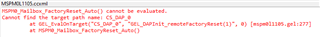
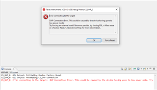
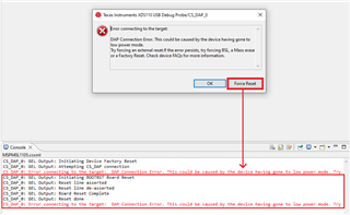
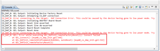
Also tried connecting the MSPM0L1105 to the XDS110 Debug Probe that comes in the evaluation board using UniFlash to program or factory reset, but I get the error "[ERROR] CS_DAP_0: Error connecting to the target: DAP Connection Error. This could be caused by the device having gone to low power mode. Try forcing an external reset.If the error persists, try forcing BSL, a Mass erase or a Factory Reset. Check device FAQs for more information."

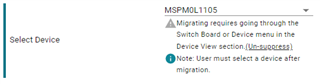
I followed this guide: /cfs-file/__key/communityserver-discussions-components-files/908/1220.Unlock-MSPM0-instructions.pdf but I'm stuck at method 1: step 5. This step lead me to method 2, which works correctly since i get the message "Send firmware successfully" and "Download complete" in green (like in the image shown in the PDF), but the MCU is in the same state as before, not programming and stuck at method 1: step 5 when trying to unlock it.

I'm not trying to write on the NVM or NONMAIN (I read that it may be the cause of the lock, though I'm not using it), it's just a simple firmware that read and write the IO and SPI pins to test that the components on the custom board are working correctly.

Note: I'm using vscode with cmake to build the firmware and J-Link via SWD to program/debug.

Thanks in advance.

  • Hi,

    1. Make sure your .cmd file and start up file has been migrated from L1306 to L1105.

    2. For factory reset, it seem that you use BSL to redownload code, but the code is for L1306 not suitable for L1105. If you have SWD and reset pin, try to follow this guide via CCS.Factory reset_Auto.pdf

    Regards,

    Zoey

  • Hi, thanks for the quick reply

    1. I didn't migrate because I created a new project in "TI System Configuration Tool". I'm building with GCC, there isn't a .cmd file. I'm using the linker file (.lds) generated by the tool with the MSPM0L1105 selected in "Select Device".

    (tried everything to solve the warning, but after selecting the device it still shows)

    My startup file is "startup_mspm0l110x_gcc.c", contained in the MSPM0 SDK v2.00.00.03 (source/ti/devices/msp/m0p/startup_system_files/gcc)

    Just in case, this is the linker file generated:

    /* Generate a link error if heap and stack don't fit into RAM */
    _Min_Heap_Size  = 0;      /* required amount of heap  */
    _Min_Stack_Size = 0x80; /* required amount of stack */
    
    /* Specify the memory areas */
    MEMORY
    {
        FLASH           (RX)  : ORIGIN = 0x00000000, LENGTH = 0x00007FF8
        SRAM            (RWX) : ORIGIN = 0x20000000, LENGTH = 0x00001000
        BCR_CONFIG      (R)   : ORIGIN = 0x41C00000, LENGTH = 0x00000080
        BSL_CONFIG      (R)   : ORIGIN = 0x41C00100, LENGTH = 0x00000080
    }
    
    /* Note: SRAM length must match MPPC/MEMSS config! Please edit it manually. */
    
    REGION_ALIAS("REGION_TEXT", FLASH);
    REGION_ALIAS("REGION_PREINIT_ARRAY", FLASH);
    REGION_ALIAS("REGION_INIT_ARRAY", FLASH);
    REGION_ALIAS("REGION_FINI_ARRAY", FLASH);
    REGION_ALIAS("REGION_BSS", SRAM);
    REGION_ALIAS("REGION_NOINIT", SRAM);
    REGION_ALIAS("REGION_DATA", SRAM);
    REGION_ALIAS("REGION_STACK", SRAM);
    REGION_ALIAS("REGION_HEAP", SRAM);
    REGION_ALIAS("REGION_TEXT_RAM", SRAM);
    REGION_ALIAS("REGION_ARM_EXIDX", FLASH);
    REGION_ALIAS("REGION_ARM_EXTAB", FLASH);
    
    /* Define output sections */
    SECTIONS
    {
        /* section for the interrupt vector area                                 */
        PROVIDE (_intvecs_base_address =
            DEFINED(_intvecs_base_address) ? _intvecs_base_address : 0x00000000);
    
        .intvecs (_intvecs_base_address) : AT (_intvecs_base_address) {
            KEEP (*(.intvecs))
        } > REGION_TEXT
    
        PROVIDE (_vtable_base_address =
            DEFINED(_vtable_base_address) ? _vtable_base_address : 0x20000000);
    
        .vtable (_vtable_base_address) (NOLOAD) : AT (_vtable_base_address) {
            KEEP (*(.vtable))
        } > REGION_DATA
    
       .text : {
            CREATE_OBJECT_SYMBOLS
            KEEP (*(.text))
            . = ALIGN(0x8);
            *(.text.*)
            . = ALIGN(0x8);
            KEEP (*(.ctors))
            . = ALIGN(0x8);
            KEEP (*(.dtors))
            . = ALIGN(0x8);
            KEEP (*(.init))
            . = ALIGN(0x8);
            KEEP (*(.fini*))
            . = ALIGN(0x8);
        } > REGION_TEXT AT> REGION_TEXT
    
        .ramfunc : {
            __ramfunct_load__ = LOADADDR (.ramfunc);
            __ramfunct_start__ = .;
           *(.ramfunc)
           . = ALIGN(0x8);
           __ramfunct_end__ = .;
        } > REGION_TEXT_RAM AT> REGION_TEXT
    
        .rodata : {
            *(.rodata)
            . = ALIGN(0x8);
            *(.rodata.*)
            . = ALIGN(0x8);
        } > REGION_TEXT AT> REGION_TEXT
    
        .preinit_array : {
            PROVIDE_HIDDEN (__preinit_array_start = .);
            KEEP (*(.preinit_array*));
            PROVIDE_HIDDEN (__preinit_array_end = .);
        } > REGION_PREINIT_ARRAY AT> REGION_TEXT
    
        .init_array : {
            . = ALIGN(0x8);
            PROVIDE_HIDDEN (__init_array_start = .);
            KEEP (*(SORT(.init_array.*)))
            KEEP (*(.init_array*))
            PROVIDE_HIDDEN (__init_array_end = .);
        } > REGION_INIT_ARRAY AT> REGION_TEXT
    
        .fini_array : {
            . = ALIGN(0x8);
            PROVIDE_HIDDEN (__fini_array_start = .);
            KEEP (*(SORT(.fini_array.*)))
            KEEP (*(.fini_array*))
            PROVIDE_HIDDEN (__fini_array_end = .);
            . = ALIGN(0x8);
        } > REGION_FINI_ARRAY AT> REGION_TEXT
    
        .ARM.exidx : {
            __exidx_start = .;
            *(.ARM.exidx* .gnu.linkonce.armexidx.*)
            __exidx_end = .;
        } > REGION_ARM_EXIDX AT> REGION_ARM_EXIDX
    
        .ARM.extab : {
            . = ALIGN(0x8);
            KEEP (*(.ARM.extab* .gnu.linkonce.armextab.*))
             . = ALIGN(0x8);
        } > REGION_ARM_EXTAB AT> REGION_ARM_EXTAB
    
        __etext = .;
    
        .data : {
            __data_load__ = LOADADDR (.data);
            __data_start__ = .;
            KEEP (*(.data))
            KEEP (*(.data*))
            . = ALIGN (8);
            __data_end__ = .;
        } > REGION_DATA AT> REGION_TEXT
    
        .bss : {
            __bss_start__ = .;
            *(.shbss)
            KEEP (*(.bss))
            *(.bss.*)
            *(COMMON)
            . = ALIGN (8);
            __bss_end__ = .;
        } > REGION_BSS AT> REGION_BSS
    
        .noinit : {
            /* place all symbols in input sections that start with .noinit */
            KEEP(*(*.noinit*))
            . = ALIGN (8);
        } > REGION_NOINIT AT> REGION_NOINIT
    
        .heap : {
            __heap_start__ = .;
            end = __heap_start__;
            _end = end;
            __end = end;
            KEEP (*(.heap))
            __heap_end__ = .;
            __HeapLimit = __heap_end__;
        } > REGION_HEAP AT> REGION_HEAP
    
        .stack (NOLOAD) : ALIGN(0x8) {
            _stack = .;
            KEEP(*(.stack))
        } > REGION_STACK AT> REGION_STACK
    
        .BCRConfig :
        {
            KEEP(*(.BCRConfig))
        } > BCR_CONFIG
    
        .BSLConfig :
        {
            KEEP(*(.BSLConfig))
        } > BSL_CONFIG
    
        __StackTop = ORIGIN(REGION_STACK) + LENGTH(REGION_STACK);
        PROVIDE(__stack = __StackTop);
    }
    

    2. I tried to follow the guide but it didn't work in my case, using J-Link and the XDS110 Debug Probe on the evaluation board (LP-MSPM0L1306) connected to the MSPM0L1105 on the custom board.

    Using J-Link, this is the error:

    Using XDS110 Debug Probe:

    When I click "Force Reset":

    When I click "OK":

    Regards.

  • Hi,

    It seems SWD can access to your core but not to DAP.

    Can you check your voltage of VCORE on yourself board?

    It seems result from hardware.

    Regards,

    Zoey

  • Hi,

    The voltage of VCORE is 1.347V. It should be good, the Hardware Development Guide says the typical voltage is 1.35V.

    I can load the firmware the first time I connect the board to the PC, it just stops connecting after the first time.

    Regards.

  • Hi,

    Sorry for late reply. 

    You mean your software is ok for MSPM0L1306 launchpad but when migrate into yourself own project, it can not work right?

    Have enable watchdog? there is one possible condition that your MCU is always reset while DSSM message is sending.

    Please try below step to confirm:

    1. Pull PA18 as power on and make MCU enter into BSL mode.

    2. Try to download or do factory reset within 10s.

    Regards,

    Zoey

  • Hi,

    I mean that the software is OK for MSPM0L1306 launchpad because I can flash/debug it everytime I want.

    But for the MSPM0L1105 on the custom board, when I flash/debug for the first time everything works. The second time I try to flash/debug the MCU is not responding.

    Watchdog is disabled. The only modules I have enabled on "TI System Configuration Tool" are GPIO, SPI, TIMER and SYSCTL (SYSCTL has everything default).

    I tried these steps but I get the same error that I showed in a previous reply.

    Regards

  • Hi

    It seems strange that once you downloaded project and then the MCU will be locked.

    Have you tried do factory reset at the first time? and then try to connect MCU at second time.

    And can you send you board's MCU part schematic? Let's rule out first whether it's due to hardware

    Regards,

    Zoey

  • Hi,

    This is the schematic

    Regards

  • HI,

    There is not problem with hardware. Can you try to read the status of MCU follow below steps?

    Read CFGAP_BOOTDIAG.pdf

    Regards,

    Zoey

  • Hi,

    I can't read those registers on the bricked MCU because I can't connect to CS_DAP_0 (DAP Connection Error).

    Not sure if this is what you want but I took a factory new custom board and read the registers on that MCU.

    Regards.

  • HI,

    It seems that your MCU SWD function has been disabled. Have you changed NONMAIN?

  • Hi,

    No, I didn't change NONMAIN. If NONMAIN has been changed, it wasn't because I wanted to do it.

    Regards.

  • Hi

    Try adding pull resistors on the SWDCLK, SWDIO lines, pull up to 3V, with a 2.2K or 4.7K resistors.

    Should make the SWD lines stable.

  • Hi,

    I tried both resistors, first 4.7k, then 2.2k but neither of them made the SWD work.

    Regards

  • After software and hardware tests, we noticed one of the I/O lines of the IC Slave was interfering with the SWDIO pin when that IC was enabled, so we will change the pin used for that I/O. Thanks for the time and patience!