Other Parts Discussed in Thread: DP83869
Tool/software:
I am using AM263Px MCU+ SDK 09.02.00 “ICSS-EMAC Lwip Example” on TMDSCNCD263P-AM263Px Sitara Control Card. I want to test that a PC connected through an unmanaged layer 2 switch (TL-SG105) can communicate with the Control Card.
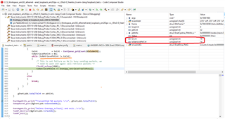
I modified only the line of code here:
#define LWIP_PORT_INIT_IPADDR(addr) IP4_ADDR((addr), 192,168,0,200)
… to:
#define LWIP_PORT_INIT_IPADDR(addr) IP4_ADDR((addr), 192,168,1,254)
... to change the IP address of the Control Card to that of my PC.
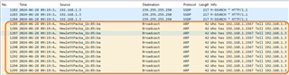
On the PC, I am running Wireshark.
I also see in the documentation that I ping is enabled. I am sending a ping request from the PC while the SDK example is running.
Note:
Enet Lwip TCP Client Example works with the same setup. I see DHCP Discover packets on Wireshark.
Questions/Issues:
1)
So far, I am not able to ping the Control Card.
If anything below does not point to a solution, please suggest troubleshooting steps.
2)
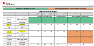
What is the switch configuration needed for SW14, SW15, and SW16? I have all switches open, but I am not certain this is correct.
3)
Although I verified that a breakpoint can be hit at:
print_cpu_load();
… I see no printf on the console.
I tried running in debug mode in both DEV_BOOT mode, and with SBL_NULL.
The Console outputs are below:
====================================
SBL_NULL
====================================
Cortex_R5_0: GEL Output: Gel files loading on R5F0 Complete
Cortex_R5_0: GEL Output: ***OnTargetConnect() Launched***
Cortex_R5_0: GEL Output: AM263Px Initialization Scripts Launched.
Please Wait...
Cortex_R5_0: GEL Output: AM263Px_Cryst_Clock_Loss_Status() Launched
Cortex_R5_0: GEL Output: Crystal Clock present
Cortex_R5_0: GEL Output: AM263Px_SOP_Mode() Launched
Cortex_R5_0: GEL Output: SOP MODE = 0x00000003
Cortex_R5_0: GEL Output:
OSPI - 8S Functional boot mode
Cortex_R5_0: GEL Output: AM263Px_Read_Device_Type() Launched
Cortex_R5_0: GEL Output: EFuse Device Type Value = 0x000000AA
Cortex_R5_0: GEL Output: AM263Px_dual_or_lockstep_mode() Launched
Cortex_R5_0: GEL Output: r5fss0 = 0x00000001
Cortex_R5_0: GEL Output: r5fss1 = 0x00000000
Cortex_R5_0: GEL Output:
R5FSS0 is in Dual core mode
Cortex_R5_0: GEL Output:
R5FSS1 is in Dual core mode
Cortex_R5_0: GEL Output: MSS_CTRL Control Registers Unlocked
Cortex_R5_0: GEL Output: MSS_TOP_RCM Control Registers Unlocked
Cortex_R5_0: GEL Output: MSS_RCM Control Registers Unlocked
Cortex_R5_0: GEL Output: MSS_IOMUX Control Registers Unlocked
Cortex_R5_0: GEL Output: TOP_CTRL Control Registers Unlocked
Cortex_R5_0: GEL Output:
*** R5FSS0 Reset DualCore ***
Cortex_R5_0: GEL Output:
***R5FSS1 Reset DualCore ***
Cortex_R5_0: GEL Output: R5F ROM Eclipse
Cortex_R5_0: GEL Output: R5FSS0_0 Released
Cortex_R5_0: GEL Output: R5FSS0_1 Released
Cortex_R5_0: GEL Output: R5FSS1_0 Released
Cortex_R5_0: GEL Output: R5FSS1_1 Released
Cortex_R5_0: GEL Output: L2 Mem Init Complete
Cortex_R5_0: GEL Output: MailBox Mem Init Complete
Cortex_R5_0: GEL Output: *********** R5FSS0/1 Dual Core mode Configured********
Cortex_R5_0: GEL Output: In ROM Setting Mode
Cortex_R5_0: GEL Output: Switch to XTAL Complete
Cortex_R5_0: GEL Output: CORE PLL Configuration Complete
Cortex_R5_0: GEL Output: SYS_CLK DIVBY2
Cortex_R5_0: GEL Output: DPLL_CORE_HSDIV0_CLKOUT0 selected as CLK source for R5FSS & SYS CLKs
Cortex_R5_0: GEL Output:
CLK Programmed R5F=400MHz and SYS_CLK=200MHz
Cortex_R5_0: GEL Output:
*** Enabling Peripheral Clocks ***
Cortex_R5_0: GEL Output: Enabling RTI[0:3] Clocks
Cortex_R5_0: GEL Output: Enabling RTI_WDT[0:3] Clocks
Cortex_R5_0: GEL Output: Enabling UART[0:5]/LIN[0:5] Clocks
Cortex_R5_0: GEL Output: Enabling QSPI Clocks
Cortex_R5_0: GEL Output: Enabling I2C Clocks
Cortex_R5_0: GEL Output: Enabling TRACE Clocks
Cortex_R5_0: GEL Output: Enabling MCAN[0:3] Clocks
Cortex_R5_0: GEL Output: Enabling MMCSD Clocks
Cortex_R5_0: GEL Output: Enabling MCSPI[0:4] Clocks
Cortex_R5_0: GEL Output: Enabling CONTROLSS Clocks
Cortex_R5_0: GEL Output: Enabling CPTS Clocks
Cortex_R5_0: GEL Output: Enabling RGMI[5,50,250] Clocks
Cortex_R5_0: GEL Output: Enabling XTAL_TEMPSENSE_32K Clocks
Cortex_R5_0: GEL Output: Enabling XTAL_MMC_32K Clocks
Cortex_R5_0: GEL Output:
***All IP Clocks are Enabled***
====================================
DEV_BOOT
====================================
Cortex_R5_0: GEL Output: Gel files loading on R5F0 Complete
Cortex_R5_0: GEL Output: ***OnTargetConnect() Launched***
Cortex_R5_0: GEL Output: AM263Px Initialization Scripts Launched.
Please Wait...
Cortex_R5_0: GEL Output: AM263Px_Cryst_Clock_Loss_Status() Launched
Cortex_R5_0: GEL Output: Crystal Clock present
Cortex_R5_0: GEL Output: AM263Px_SOP_Mode() Launched
Cortex_R5_0: GEL Output: SOP MODE = 0x0000000B
Cortex_R5_0: GEL Output:
DevBoot mode
Cortex_R5_0: GEL Output: AM263Px_Read_Device_Type() Launched
Cortex_R5_0: GEL Output: EFuse Device Type Value = 0x000000AA
Cortex_R5_0: GEL Output: AM263Px_dual_or_lockstep_mode() Launched
Cortex_R5_0: GEL Output: r5fss0 = 0x00000101
Cortex_R5_0: GEL Output: r5fss1 = 0x00000100
Cortex_R5_0: GEL Output:
R5FSS0 is in Lockstep mode
Cortex_R5_0: GEL Output:
R5FSS1 is in Lockstep mode
Cortex_R5_0: GEL Output: MSS_CTRL Control Registers Unlocked
Cortex_R5_0: GEL Output: MSS_TOP_RCM Control Registers Unlocked
Cortex_R5_0: GEL Output: MSS_RCM Control Registers Unlocked
Cortex_R5_0: GEL Output: MSS_IOMUX Control Registers Unlocked
Cortex_R5_0: GEL Output: TOP_CTRL Control Registers Unlocked
Cortex_R5_0: GEL Output:
*** R5FSS0 Reset DualCore ***
Cortex_R5_0: GEL Output:
***R5FSS1 Reset DualCore ***
Cortex_R5_0: GEL Output: R5F ROM Eclipse
Cortex_R5_0: GEL Output: R5FSS0_0 Released
Cortex_R5_0: GEL Output: R5FSS0_1 Released
Cortex_R5_0: GEL Output: R5FSS1_0 Released
Cortex_R5_0: GEL Output: R5FSS1_1 Released
Cortex_R5_0: GEL Output: L2 Mem Init Complete
Cortex_R5_0: GEL Output: MailBox Mem Init Complete
Cortex_R5_0: GEL Output: *********** R5FSS0/1 Dual Core mode Configured********
Cortex_R5_0: GEL Output: In ROM Setting Mode
Cortex_R5_0: GEL Output: Switch to XTAL Complete
Cortex_R5_0: GEL Output: CORE PLL Configuration Complete
Cortex_R5_0: GEL Output: PER PLL Configuration Complete
Cortex_R5_0: GEL Output: SYS_CLK DIVBY2
Cortex_R5_0: GEL Output: DPLL_CORE_HSDIV0_CLKOUT0 selected as CLK source for R5FSS & SYS CLKs
Cortex_R5_0: GEL Output:
CLK Programmed R5F=400MHz and SYS_CLK=200MHz
Cortex_R5_0: GEL Output:
*** Enabling Peripheral Clocks ***
Cortex_R5_0: GEL Output: Enabling RTI[0:3] Clocks
Cortex_R5_0: GEL Output: Enabling RTI_WDT[0:3] Clocks
Cortex_R5_0: GEL Output: Enabling UART[0:5]/LIN[0:5] Clocks
Cortex_R5_0: GEL Output: Enabling QSPI Clocks
Cortex_R5_0: GEL Output: Enabling I2C Clocks
Cortex_R5_0: GEL Output: Enabling TRACE Clocks
Cortex_R5_0: GEL Output: Enabling MCAN[0:3] Clocks
Cortex_R5_0: GEL Output: Enabling MMCSD Clocks
Cortex_R5_0: GEL Output: Enabling MCSPI[0:4] Clocks
Cortex_R5_0: GEL Output: Enabling CONTROLSS Clocks
Cortex_R5_0: GEL Output: Enabling CPTS Clocks
Cortex_R5_0: GEL Output: Enabling RGMI[5,50,250] Clocks
Cortex_R5_0: GEL Output: Enabling XTAL_TEMPSENSE_32K Clocks
Cortex_R5_0: GEL Output: Enabling XTAL_MMC_32K Clocks
Cortex_R5_0: GEL Output:
***All IP Clocks are Enabled***
====================================
Regards,
Tollman