Part Number: LP-AM243
Other Parts Discussed in Thread: TMDS243EVM, TMDS64DC01EVM
Tool/software:
Hello Nick Saulnier
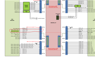
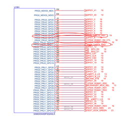
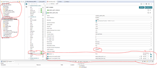
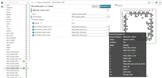
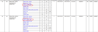
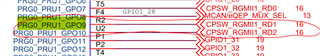
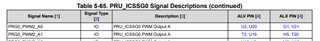
I'm working with the PRU on the AM243 and have been trying to run the PRU hardware UART example for a few days. I have reviewed almost all the past issues related to PRU UART on the ti forum but have not reached a conclusion. I used the .cmd and pru_uart.h files from the AM64. I did the pinmux settings via CCS, but I couldn't get a result. I'm new to PRU at TI and would be very grateful for your help. The files I'm using and the necessary photos are attached.
First I load the code into the r core. Then I run the m core, disconnect it and load the pru code into the iccsg0 pru 0 core. pru_hardware.uart.c:
#include <stdint.h>#include <pru_uart.h>
#define FIFO_SIZE 16#define MAX_CHARS 8
struct { uint8_t msg; // Not used today uint8_t data[FIFO_SIZE];} hostBuffer;
uint8_t buffer[MAX_CHARS];
void main(void){ uint8_t tx; uint8_t cnt;
CT_UART.DIVLSB_bit.DLL = 104; // CT_UART.DIVLSB = 104; CT_UART.DIVMSB_bit.DLH = 0;//CT_UART.DIVMSB = 0; CT_UART.MODE = 0x0;
CT_UART.INT_EN = 0x7;
/* TODO: Add 8-byte RX FIFO trigger */ //CT_UART.FCR = (0x8) | (0x4) | (0x2) | (0x1); /* AM335x: FCR, set to 0xF */ CT_UART.FCR = (0x80) | (0x4) | (0x2) | (0x01); // 8-byte RX FIFO trigger
CT_UART.LCTR = 3; // CT_UART.LCTR = 3; /* AM335x: LCR */
CT_UART.MCTR = 0x10;
CT_UART.PWR = 0x6001;
hostBuffer.data[0] = 'H'; hostBuffer.data[1] = 'e'; hostBuffer.data[2] = 'l'; hostBuffer.data[3] = 'l'; hostBuffer.data[4] = 'o'; hostBuffer.data[5] = '!'; hostBuffer.data[6] = '\0';
for (cnt = 0; cnt < MAX_CHARS; cnt++) {
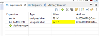
if ((tx = hostBuffer.data[cnt]) == '\0') break;
CT_UART.THR = tx;
//while ((CT_UART.LSR1_bit.DR == 0x0)); while ((CT_UART.LSR1 & 0x1) == 0x0);
buffer[cnt] = CT_UART.RBR; // buffer[cnt] = CT_UART.RBR_TBR_bit.RBR_DATA; /* AM335x: RBR */
/* Wait for TX FIFO to be empty */ while (!((CT_UART.FCR & 0x2) == 0x2)); //while (!((CT_UART.IIR_bit.INTID) == 0x1)); // while (!((CT_UART.INT_FIFO_bit.IIR_INTID) == 0x1)); /* AM335x: FCR */ /* original code: while (!((CT_UART.FCR & 0x2) == 0x2)); */ /* TODO: Since this is a read, IIR should be used, not FCR. I assume they meant to put while (!((CT_UART.IIR & 0x2) == 0x2)); */ }
CT_UART.PWR = 0x0;
__halt();}
pru_uart.h:
#ifndef _PRU_UART_H_#define _PRU_UART_H_
/* PRU UART register set */typedef struct {
/* * PRU_UART_RBR_TBR register bit field * RBR and TBR / THR register pair * * This is a unique register pair in that RBR and THR * share the same address. RBR is read-only while THR is * write-only. * * Additionally, RBR and THR share an address with DLL. To * read/write RBR/THR write 0 to the DLAB bit in the LCR * register. To modify DLL write a 1. * * DLL also has a dedicated * address which does not require toggling the DLAB bit. */ union { /* PRU_UART_RBR register bit field */ union { volatile uint32_t RBR;
volatile struct { unsigned DATA : 8; // 7:0 unsigned rsvd8 : 24; // 31:8 } RBR_bit; };
/* PRU_UART_THR register bit field */ union { volatile uint32_t THR;
volatile struct { unsigned DATA : 8; // 7:0 unsigned rsvd8 : 24; // 31:8 } THR_bit; }; }; // 0x0
/* PRU_UART_INT_EN register bit field */ union { volatile uint32_t INT_EN;
volatile struct { uint32_t ERBI : 1; // 0 uint32_t ETBEI : 1; // 1 uint32_t ELSI : 1; // 2 uint32_t EDSSI : 1; // 3 uint32_t rsvd4 : 28; // 31:4 } INT_EN_bit; }; // 0x4
/* * IIR and FCR register pair * This is a unique register pair in that IIR and FCR * share the same address. IIR is read-only while FCR is * write-only. */ union { /* PRU_UART_IIR register bit field */ union { volatile uint32_t IIR;
volatile struct { unsigned IPEND : 1; // 0 unsigned INTID : 3; // 3:1 unsigned rsvd4 : 2; // 5:4 unsigned FIFOEN : 2; // 7:6 unsigned rsvd8 : 24; // 31:8 } IIR_bit; };
/* PRU_UART_FCR register bit field */ union { volatile uint32_t FCR;
volatile struct { unsigned FIFOEN : 1; // 0 unsigned RXCLR : 1; // 1 unsigned TXCLR : 1; // 2 unsigned DMAMODE1 : 1; // 3 unsigned rsvd4 : 2; // 5:4 unsigned RXFIFTL : 2; // 7:6 unsigned rsvd8 : 24; // 31:8 } FCR_bit; }; }; // 0x8
/* PRU_UART_LCTR register bit field */ union { volatile uint32_t LCTR;
volatile struct { uint32_t WLS0 : 1; // 0 uint32_t WLS1 : 1; // 1 uint32_t STB : 1; // 2 uint32_t PEN : 1; // 3 uint32_t EPS : 1; // 4 uint32_t SP : 1; // 5 uint32_t BC : 1; // 6 uint32_t DLAB : 1; // 7 uint32_t rsvd8 : 24; // 31:8 } LCTR_bit; }; // 0xc
/* PRU_UART_MCTR register bit field */ union { volatile uint32_t MCTR;
volatile struct { uint32_t DTR : 1; // 0 uint32_t RTS : 1; // 1 uint32_t OUT1 : 1; // 2 uint32_t OUT2 : 1; // 3 uint32_t LOOP : 1; // 4 uint32_t AFE : 1; // 5 uint32_t rsvd6 : 26; // 31:6 } MCTR_bit; }; // 0x10
/* PRU_UART_LSR1 register bit field */ union { volatile uint32_t LSR1;
volatile struct { uint32_t DR : 1; // 0 uint32_t OE : 1; // 1 uint32_t PE : 1; // 2 uint32_t FE : 1; // 3 uint32_t BI : 1; // 4 uint32_t THRE : 1; // 5 uint32_t TEMT : 1; // 6 uint32_t RXFIFOE : 1; // 7 uint32_t rsvd8 : 24; // 31:8 } LSR1_bit; }; // 0x14
/* PRU_UART_MSR register bit field */ union { volatile uint32_t MSR;
volatile struct { uint32_t DCTS : 1; // 0 uint32_t DDSR : 1; // 1 uint32_t TERI : 1; // 2 uint32_t DCD : 1; // 3 uint32_t CTS : 1; // 4 uint32_t DSR : 1; // 5 uint32_t RI : 1; // 6 uint32_t CD : 1; // 7 uint32_t rsvd8 : 24; // 31:8 } MSR_bit; }; // 0x18
/* PRU_UART_SCRATCH register bit field */ union { volatile uint32_t SCRATCH;
volatile struct { uint32_t DATA : 8; // 7:0 uint32_t rsvd8 : 24; // 31:8 } SCRATCH_bit; }; // 0x1c
/* PRU_UART_DIVLSB register bit field */ union { volatile uint32_t DIVLSB;
volatile struct { uint32_t DLL : 8; // 7:0 uint32_t rsvd8 : 24; // 31:8 } DIVLSB_bit; }; // 0x20
/* PRU_UART_DIVMSB register bit field */ union { volatile uint32_t DIVMSB;
volatile struct { uint32_t DLH : 8; // 7:0 uint32_t rsvd8 : 24; // 31:8 } DIVMSB_bit; }; // 0x24
/* PRU_UART_PID register bit field */ union { volatile uint32_t PID;
volatile struct { uint32_t PID : 32; // 31:0 } PID_bit; }; // 0x28
uint8_t rsvd2c[4]; // 0x2c - 0x2f
/* PRU_UART_PWR register bit field */ union { volatile uint32_t PWR;
volatile struct { uint32_t FREE : 1; // 0 uint32_t RES : 1; // 1 uint32_t rsvd2 : 11; // 12:2 uint32_t URRST : 1; // 13 uint32_t UTRST : 1; // 14 uint32_t URST : 1; // 15 uint32_t rsvd16 : 16; // 31:16 } PWR_bit; }; // 0x30
/* PRU_UART_MODE register bit field */ union { volatile uint32_t MODE;
volatile struct { uint32_t OSM_SEL : 1; // 0 uint32_t rsvd1 : 31; // 31:1 } MODE_bit; }; // 0x34
} uart;
volatile __far uart CT_UART __attribute__((cregister("PRU_UART", far), peripheral));
#endif /* _PRU_UART_H_ */
.cmd :
/* * AM64x_PRU0.cmd * * Example Linker command file for linking programs built with the C compiler * on AM64x PRU0 cores * * Copyright (C) 2021-2022 Texas Instruments Incorporated - https://www.ti.com/ * * Redistribution and use in source and binary forms, with or without * modification, are permitted provided that the following conditions * are met: * * * Redistributions of source code must retain the above copyright * notice, this list of conditions and the following disclaimer. * * * Redistributions in binary form must reproduce the above copyright * notice, this list of conditions and the following disclaimer in the * documentation and/or other materials provided with the * distribution. * * * Neither the name of Texas Instruments Incorporated nor the names of * its contributors may be used to endorse or promote products derived * from this software without specific prior written permission. * * THIS SOFTWARE IS PROVIDED BY THE COPYRIGHT HOLDERS AND CONTRIBUTORS * "AS IS" AND ANY EXPRESS OR IMPLIED WARRANTIES, INCLUDING, BUT NOT * LIMITED TO, THE IMPLIED WARRANTIES OF MERCHANTABILITY AND FITNESS FOR * A PARTICULAR PURPOSE ARE DISCLAIMED. IN NO EVENT SHALL THE COPYRIGHT * OWNER OR CONTRIBUTORS BE LIABLE FOR ANY DIRECT, INDIRECT, INCIDENTAL, * SPECIAL, EXEMPLARY, OR CONSEQUENTIAL DAMAGES (INCLUDING, BUT NOT * LIMITED TO, PROCUREMENT OF SUBSTITUTE GOODS OR SERVICES; LOSS OF USE, * DATA, OR PROFITS; OR BUSINESS INTERRUPTION) HOWEVER CAUSED AND ON ANY * THEORY OF LIABILITY, WHETHER IN CONTRACT, STRICT LIABILITY, OR TORT * (INCLUDING NEGLIGENCE OR OTHERWISE) ARISING IN ANY WAY OUT OF THE USE * OF THIS SOFTWARE, EVEN IF ADVISED OF THE POSSIBILITY OF SUCH DAMAGE. */
-cr /* Link using C conventions */
/* Specify the System Memory Map */MEMORY{ PAGE 0: /* 12 KB PRU Instruction RAM */ PRU_IMEM : org = 0x00000000 len = 0x00003000
PAGE 1: /* Data RAMs */ /* 8 KB PRU Data RAM 0; use only the first 4 KB for PRU0 and reserve * the second 4 KB for RTU0 and Tx_PRU0 */ PRU0_DMEM_0 : org = 0x00000000 len = 0x00001000 CREGISTER=24 /* 8 KB PRU Data RAM 1; reserved completely for Slice1 cores - PRU1, * RTU1 and Tx_PRU1; do not use for any Slice0 cores */ PRU0_DMEM_1 : org = 0x00002000 len = 0x00001000 CREGISTER=25 /* NOTE: Custom split of the second 4 KB of ICSS Data RAMs 0 and 1 * split equally between the corresponding RTU and Tx_PRU cores in * each slice */ RTU0_DMEM_0 : org = 0x00001000 len = 0x00000800 TX_PRU0_DMEM_0 : org = 0x00001800 len = 0x00000800 RTU0_DMEM_1 : org = 0x00003000 len = 0x00000800 TX_PRU0_DMEM_1 : org = 0x00003800 len = 0x00000800
PAGE 2: /* C28 needs to be programmed to point to SHAREDMEM, default is 0 */ /* 64 KB PRU Shared RAM */ PRU_SHAREDMEM : org = 0x00010000 len = 0x00010000 CREGISTER=28
/* Internal Peripherals */ /* NOTE: Use full INTC length instead of 0x200 to match the pruIntc * structure definition in pru_intc.h, ignoring the second Constant * Register #6 that starts at 0x200 offset within INTC */ PRU_INTC : org = 0x00020000 len = 0x00001504 CREGISTER=0 PRU_IEP1 : org = 0x0002F000 len = 0x00000100 CREGISTER=1 PRU_IEP1_0x100 : org = 0x0002F100 len = 0x0000021C CREGISTER=2 PRU_ECAP : org = 0x00030000 len = 0x00000060 CREGISTER=3 PRU_CFG : org = 0x00026000 len = 0x00000100 CREGISTER=4 PRU_CFG_0x100 : org = 0x00026100 len = 0x00000098 CREGISTER=5 /* XXX: PRU_INTC_0x200 is part of INTC space, and is therefore commented * out as it conflicts with PRU_INTC size above. To use PRU_INTC_0x200, * split up the pruIntc structure and CT_INTC variable in * include/PROCESSOR/pru_intc.h */ /*PRU_INTC_0x200: org = 0x00020200 len = 0x00001304 CREGISTER=6*/ PRU_UART : org = 0x00028000 len = 0x00000038 CREGISTER=7 PRU_IEP0_0x100 : org = 0x0002E100 len = 0x0000021C CREGISTER=8 MII_G_RT : org = 0x00033000 len = 0x00000F44 CREGISTER=9 TM_CFG_PRU0 : org = 0x0002A000 len = 0x0000004C CREGISTER=10 PRU0_CTRL : org = 0x00022000 len = 0x00000030 CREGISTER=11 PA_STATS_QRAM : org = 0x00027000 len = 0x00001000 CREGISTER=12 PA_STATS_CRAM : org = 0x0002C000 len = 0x00001000 CREGISTER=13 MII_MDIO : org = 0x00032400 len = 0x00000088 CREGISTER=21 PRU_RTU_RAT0 : org = 0x00008000 len = 0x00000854 CREGISTER=22 PRU_IEP0 : org = 0x0002E000 len = 0x00000100 CREGISTER=26 MII_RT : org = 0x00032000 len = 0x00000070 CREGISTER=27
/* External Regions */ /* Random length 0x100 assigned to the below regions */ RSVD14 : org = 0x00024800 len = 0x00000100 CREGISTER=14 RSVD15 : org = 0x60000000 len = 0x00000100 CREGISTER=15 RSVD16 : org = 0x70000000 len = 0x00000100 CREGISTER=16 RSVD17 : org = 0x80000000 len = 0x00000100 CREGISTER=17 RSVD18 : org = 0x90000000 len = 0x00000100 CREGISTER=18 RSVD19 : org = 0xA0000000 len = 0x00000100 CREGISTER=19 RSVD20 : org = 0xB0000000 len = 0x00000100 CREGISTER=20 RSVD23 : org = 0xC0000000 len = 0x00000100 CREGISTER=23 /* Random length 0x10000 (max len value) assigned to programmable C29-31*/ RSVD29 : org = 0xD0000000 len = 0x00010000 CREGISTER=29 RSVD30 : org = 0xE0000000 len = 0x00010000 CREGISTER=30 RSVD31 : org = 0xF0000000 len = 0x00010000 CREGISTER=31}
/* Specify the sections allocation into memory */SECTIONS { /* Forces _c_int00 to the start of PRU IRAM. Not necessary when loading an ELF file, but useful when loading a binary */ .text:_c_int00* > 0x0, PAGE 0
.text > PRU_IMEM, PAGE 0 .stack > PRU0_DMEM_0, PAGE 1 .bss > PRU0_DMEM_0, PAGE 1 .cio > PRU0_DMEM_0, PAGE 1 .data > PRU0_DMEM_0, PAGE 1 .switch > PRU0_DMEM_0, PAGE 1 .sysmem > PRU0_DMEM_0, PAGE 1 .cinit > PRU0_DMEM_0, PAGE 1 .rodata > PRU0_DMEM_0, PAGE 1 .rofardata > PRU0_DMEM_0, PAGE 1 .farbss > PRU0_DMEM_0, PAGE 1 .fardata > PRU0_DMEM_0, PAGE 1}