MSPM0G3507: BSL, LIN, UART0 - overlapping pin selections

Part Number: MSPM0G3507
Other Parts Discussed in Thread: SYSCONFIG

Tool/software:

Hello my dear supporters and engineers,

I am currently designing a PCB with MSPM0G3507.

And I am concerned about some maybe overlapping pin selection/usage.

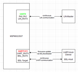
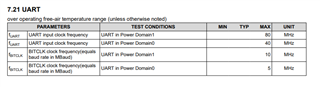
I have to use UART0 for LIN-Communication.

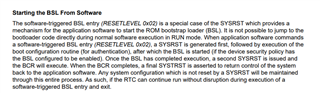
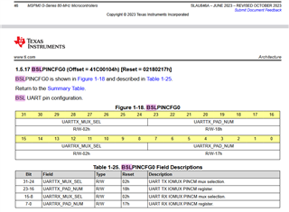
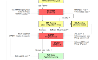
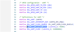
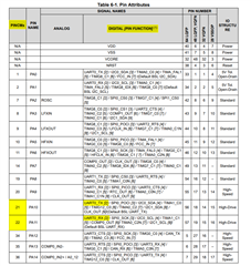
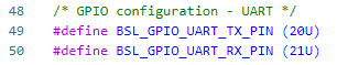
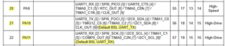
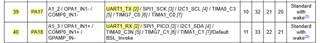
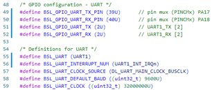
Furthermore I want to use a Bootloader which requires the usage of Default BSL UART_RX/TX of pins PA10 and PA11, to implement a firmware update via UART from my external host device.

Apart from that I want to use these pins for regular UART-Communication with my host device.

As I can't use UART0, that is mappable to these pins PA10 and PA11, can I use the BSL-UART-pins for regular communication AND for Bootloader-Data-transfer?

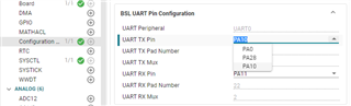
Or can I map BSL UART_RX/TX to any other pin?  Or why does it say "default"? It sounds as if it can be mapped to some other pin.

Thanks a lot in advance!

If you need any further information - feel free to ask!

Matze

  • Hi Matze,

    The default BSL is based on the factory default conditions, you can change these pins in NONMAIN under the BSLPINCFG0 register. We have a module in SysConfig called Configuration NVM that should assist on a programming level for how to configure other UART pins.

    BSL, typically, is a separate process flow from your main application, so I would say you should be able to do both the LIN and BSL on the same UART pins. Just make sure to use the BSL invoke pin from a device reset to enter the bootloader. 

    Regards,
    Luke

  • Hi Luke,

    thanks for you answers!

    1. Good to know that the BSL UART_RX/TX can be mapped to any UART0 pin. I didn't find that information in the datasheet. Can you tell me where to find it?
    2. I'm afraid I didn't make myself totally clear.
      1. I want to use LIN-functionality on two pins (RX and TX).
      2. And I want to use two other pins for regular UART-Communication with my host device.
      3. And I want to use BSL UART_RX/TX on the same two pins that are used for regular UART-Communication with my host device because I want my host device to be the master for the firmware-update via UART and bootloader.
      4. When I try to make these configurations in the .syscfg-tab in CCS Theia I get a "ressource conflict".
      5. Is this configuration in any way possible?
    3. Can I map LIN functionality on any other pins apart from UART0 pins, because UART0 is essentially required for BSL (and regular UART-Communication)?
    4. Or can I map BSL functionality on any other pins apart from UART0 pins, because UART0 is essentially required for LIN?
    5. Is there a possibility to use software UART for BSL? e.g.:
      1. software-uart for regular UART-Communication on BSL-capable-pins
      2. incoming UART message for start of BSL
      3. deactivating LIN at runtime
      4. mapping UART0-BSL from the LIN-pins to the regular UART-Communication-pins
      5. activating BSL at runtime in the BSLPINCFG0 register
      6. making firmware update via host device, UART and bootloader
      7. reversing all the controller configurations back to normal operation
    6. Or can I use software UART for LIN-Communication?
    7. Do I need to use the hardware BSL invoke pin as you wrote in your above message or can I use the software invoke functionality?
    8. If my configuration ideas really exclude each other - can you recommend any other controller to me where LIN and BSL do not exclude each other and that have the same amount of pins and functionalities?

    and once again..

    thanks a lot in advance for your answers!

    Matze

  • Hi Matze,

    1. The BSL information is in the G-Series Technical Reference Manual section 1.4 Boot Configuration and 1.5 NONMAIN Registers
    2. There are multiple UART on this device, with only UART0 available for LIN. The other 3 UART are available for normal UART communication and can be used for BSL if reconfigured in NONMAIN.
      1. The default BSL UART is UART0 so that would be your LIN UART.
      2. If intending to have your LIN completely separate from your BSL then I suggest reconfiguring the BSL UART pins to some non-UART0 peripheral. (PA8 and PA9 could work)
      3. Can you share where exactly you get the resource conflict? You might need to switch which UART peripheral you are using. Also on the top right, there is a (i) symbol which can give more information on the error.
    3. UART0 is the only LIN enabled UART peripheral on this device.
    4. Yes, the BSL can be mapped to different pins
    5. What do you mean by software UART? Are you meaning bit-banging normal GPIO pins?
      1. If yes, you could do this by making a secondary BSL but I wouldn't recommend it. Much easier to use a different UART peripheral.
    6. -
    7. You can use software reset if you want to enter while running, this would cause a SYSRST. I suggest reading chapter 2.4.1 to understand the reset states.

    The current device can do what you need based on the configurations. BSL is a separate process and unless you do a secondary BSL, the related peripherals and pins would get reset. Secondary BSL can allow you to have a more custom/unique scenario but I don't think you'll need to do that.

    Here's a document tailored to the Bootloader on MSPM0 -> MSPM0 Bootloader User's Guide

    Regards,
    Luke

  • Hi Luke,

    once again thank you for your answers!

    1. I read the recommended manual over and over but I could not find any information about on which UARTs and pins the BSL_RX/TX can be mapped. Can you please send me a screenshot?
    2. Can you please describe in detail where/how to reconfigure the UART1/2/3 and corresponding pins in NONMAIN to be used for BSL?
      1. Yes in my SysConfig Editor view of the .syscfg-file I select UART0 (PA0 and PA1) for LIN.
      2. I try to reconfigure BSL UART pins to some non-UART0 peripheral but the BSL UART Pin Configuration in "Configuration NVM" only shows/allows/offers UART0 and corresponding Pins. Please explain, how and where to reconfigure BSL to UART1/2/3.

        1. If I manually change the BSL UART PINs in Code Editor view of the .syscfg-file to PA8 and PA9 ...

          ... I get build errors:
      3. The error came up when I tried out the configurations in some example projects. I guess UART0 was used for some other peripheral. Full error message behind the (i)-button was "ressource conflict". But now I created a new empty project and I don't get this error.
    3. Okay, that's what I expected.
    4. Okay, that's what I was hoping for .. but I can't figure out how ..
    5. Yes I was thinking of bit-ganging as software UART - but I would be really glad not to use bit-banging and simply to map BSL to UART1/2/3!
    6. -
    7. Yes, thanks. I guess both software reset and reset by invoke pin will cause a SYSRST to be able to enable the BSL-procedure. Am I right?
    8. I found some hint where I might configure the Pins/UARTs.. but I still don't understand, how to do so.. if that is the right register at all..

    and once again..

    thanks a lot in advance for your answers!

    Matze

  • Hi Matze,

    Looking into the ROM BSL further, the ROM BSL uses UART0 by default, so unless you create a secondary BSL, it will always use UART0. Sorry for the confusion on the ROM BSL.

    Since UART0 is used for both ROM BSL and LIN, I would change the UART0 assignment to different pins while using LIN (any pins would work). So save PA10 and PA11 for your BSL interface and set a different pair of UART0 RX and TX pins to the LIN transceiver. ROM BSL happens only after a peripheral reset state, so this will have your UART0 and IOMUX(s) reset and set to PA10/PA11 during the BCR stage. You won't need to adjust the Configuration Non-main module through this.

    Hope this helps with the process flow!

    Regards,
    Luke

  • Hi Luke,

    oh no.. I was so hoping that you would explain any solution to me how I can use ROM BSL with any other UART like UART1/2/3 apart from UART0.

    Unfortunately you are forgetting that I have to use the BSL-UART-Pins during normal operation for regular UART communication with my host device.

    And that's why I have to use UART1/2/3-pins for BSL because I can't use UART0 both for continuous LIN communication and continuous regular UART communication with my host device.

    I have drawn a diagram of my desired/required constellation to hopefully make my point/problem totally clear to you.

    So I draw the following conclusion from our conversation so far:

    1. I am forced to use the secondary BSL to be able to map the BSL-functionality to UART1/2/3-Pins and not to any UART0-Pins. Am I right?
    2. Can you explain to me, step by step, all-embracing how I can set up a secondary BSL on MSPM0G3507 that uses UART1 or 2 or 3?
    3. I imported the example project "secondary_bsl_uart_LP_MSPM0G3507_nortos_ticlang" into CCS Theia but the "secondary_bsl.syscfg" issues the following warning: "Project Configuration File generation is disabled for this project. SysConfig Project Migration is not currently supported for this project."
      1. Is secondary BSL not possible with support by .SysCfg - File-Generation?
      2. Or does this warning come up because of any other constellation apart from secondary BSL?
      3. Why is Project Configuration File Generation disabled for this project?
      4. And can I somehow enable it?
    4. I really need a step by step explanation or a tutorial that guides me through setting up a MSPM0G3507 software project that uses software BSL on UART1/2/3, UART-Communication on the same UART and pins and LIN on UART0-Pins. Can you please assist me in this matter?

    .. and once again..

    Thanks a lot in advance for your answers!

    Matze

  • Hi Matze,

    This project was created before SysConfig had file generation options initially. The secondary BSL does have specifics in the startup file and linker file, which you do not want SysConfig to generate. This is because the secondary BSL was created to replace the ROM BSL, so it has special memory formatting to guarantee memory locations of the BSL processes. The startup file is missing some handlers, so I would make sure the peripherals you may need are included in the startup file. (You can look at another examples start up file to find the missing handlers).

    You can still use SysConfig to assist in your project. I would take the ti_msp_config files that are currently used and rename them (make sure to change the #include as well). There are going to be duplicate functions that have the WEAK property that you'll need to rename as well so you can use them. In the Sysconfig file, make sure the linker and startup files are not generated by SysConfig. This should be all that's needed to change to get SysConfig enabled in the project.

    I'm looking at the file now and it looks like it has all the references to the many possible BSL interfaces, you can delete those if it'll help with readability (CAN, SPI, I2C).

    In ti_msp_dl_config.h change lines 48-59 to be for your UART configuration.

    The MSPM0 Bootloader's User's Guide has some details on section 6 Secondary Bootloader.

    Regards,
    Luke

  • Thanks Luke,

    it sounds very complex what files to keep, rename, modify. What files to generate, what files not to generate and to write by myself.

    1. What do you mean by some missing handlers in the startup file?
    2. Do I have to make the linker and startup files on my own as they are not generated by SysCfg?
    3. Can I configure/use any UART1/2/3 capable Pins for BSL-UART in a secondary BSL configuration?
    4. Or are there only some special Pins available for that?
    5. I would like to use UART1 - PA17 (Pin 32) and PA18 (Pin 33) for RX & TX. Is this possible?

    Thanks in advance!

    Matze

  • Hi Matze,

    It sounds like a lot before looking into it but you'll quickly find what's needed when you open the example and view the files.

    1. I opened up the startup file and saw it didn't have every handler, which you can compare to an existing example to add what you needed.
    2. The linkerfile from the secondary BSL example should be enough for you, the start up file might need some slight adjustments according to your need.
    3. Any UART will work here, just to give some background. The ROM BSL which is default is in the read only memory of the device, this secondary BSL will be in your MAIN flash and is fully customizable as it is freeform code you are adding. What happens is during some process you can do the secondary BSL.
    4. In my previous message I listed the lines you'll need to change for a different UART configuration.

    Regards,
    Luke

  • Can I also change the baudrate in line 58 of the ti_msp_dl_config.h?

    And if I can cange it.. is there any limitation in speed? any max baud rate?

    Even though the define's name is BSL_UART_DEFAULT_BAUD?

    Can I rename it to something like BSL_UART_BAUD ?

  • And can you please explain to me what's the meaning of these two lines?

    #define BSL_GPIO_UART_TX (2U)
    #define BSL_GPIO_UART_RX (2U)
    What does the 2U mean?
    Do I have to change these values if I change to other pins and to UART1 or UART2?
  • Hi Matze,

    You can rename the #define BSL_UART_DEFAULT_BAUD (make sure you also go to where this define is being used and change the name there too.. you'll probably get a compile error)

    The speed limitation is the same as in the device. Default clock is 32 Mhz and with 8x oversampling that would be 4MHz. I would personally do 16x oversampling (more oversampling will help filter out noise but that all depends on your system.


    For 2U, the U means unsigned int and 2 is the value. This value is the Pin Function value for UART on those pins.

    For "BSL_GPIO_UART_TX_PIN" the value is the pin mux value of 21 which corresponds to PA10 and the BSL_GPIO_UART_TX is set to 2 because this is the pin function value for UART on this chosen pin.

    If you look into where these defines are being used you'll see more context and how to use these if you're looking to program other pins.

    Regards,
    Luke

  • Hi Luke,

    thanks again!

    Concerning the "2U" in the UART Pin Config... I could and should have known that..

    Just one additional question about baudrate:

    I guess my desired Baud Rate of 460.800 bit/s or 115.200 bit/s should be no problem.

    32 MHz with 16x oversampling results in a max. baudrate of 2 MHz = 2.000.000 bit/s, right?

    Regards,
    Matze

  • And once again another question:

    It seems like the Pin-config in the example contradicts the datasheet..

    The example uses the pin mux values 20 and 21.

    When I look into the datasheet I would chose pin mux values 21 and 22.

    But the flashing via BSL_GUI_EXE is working. Can you explain that to me?

    I would like to use UART1 - PA17 (Pin 32) and PA18 (Pin 33).

    Is this the correct pin mux config?

    Or do I have to decrease 39U to 38U and 40U to 39U, like 21 and 22 are decreased to 20 and 21 in the example?

    Thanks a lot in advance!

    Matze

  • Hi Matze,

    The IOMUX starts its index at 1, whereas the array that is built for the IOMUX in code is indexed at 0. So the IOMUX - 1 will be the correct value in order to fit into the array.

    Your calculations for Max baud rate at 32MHz clock and 16x oversampling is correct at 2MHz.

    Regards,
    Luke