This thread has been locked.
If you have a related question, please click the "Ask a related question" button in the top right corner. The newly created question will be automatically linked to this question.
Tool/software:
Hello,
I have designed a custom board using TM4C123AE6PM. I want to program TM4C over usb port. To do that i used the below circuit.. But when i connect the custom board to usb port of laptop pb1 port burned in a few seconds.I guess it is because 5Vdc on port1 of usb.
by the way at the beginning: the mcu was empty. not programmed.
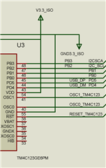
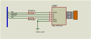
Then i dropped the voltage to 3.3Vdc with a voltage divider I made from resistors(4K7 AND 10K). I also connected 1k resistors in series to the PB0 DM and DP ports (to limit the the current). PB1 did not burn, but laptop's USB port did not detect the TM4C custom card (I used a new custom board, not the damaged one).
Thanks in advance for your help.
Regards
Erdem
Hi,
Please refer to TM4C123 System Design Guideline for PB1 pin used as VBUS signal. I think what happens is that before PB1 is configured as a VBUS input, it was by default a GPIO pin which is NOT 5V tolerant. This is why the pin is damage. Please follow the recommended protection on PB1 using a 100ohm series resistor.
4.1.1 USB Device Only For TM4C123x devices that are used in a device-only configuration, the only signal used in addition to USB0DM and USB0DP is USB0VBUS, which is located on port PB1. In USB device-only mode, USB0VBUS is used to detect when voltage has been applied to or removed from the USB connector, which triggers software to manage the internal USB PHY accordingly. When configured as USB0VBUS, this pin is 5-V tolerant. However, when used as a GPIO input, PB1 is NOT 5-V tolerant. An alternate 5-V tolerant Fail-Safe GPIO should be selected to do the VBUS detection if there is a chance 5V could be applied to the input prior to PB1 on the TM4C123x device being configured for VBUS, such as during power-up, while the device is in reset, and the while the initial boot sequence executes. For a USB device-only configuration, a 100Ω resistor should be placed in series between VBUS on the USB connector and PB1 (or alternate 5-V tolerant GPIO) on the microcontroller in order to limit damage caused by any ESD events. If PB1 must be used for a function other than USB0VBUS, any other available 5-V tolerant Fail-Safe GPIO could be used in its place.