This thread has been locked.

If you have a related question, please click the "Ask a related question" button in the top right corner. The newly created question will be automatically linked to this question.

TM4C1294NCPDT: connection fail with XDS110 FW

Part Number: TM4C1294NCPDT
Other Parts Discussed in Thread: AWR2243, UNIFLASH

Tool/software:

Dear Champs,

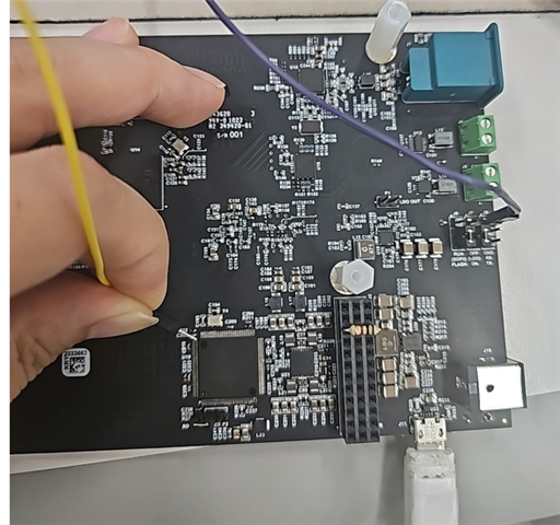
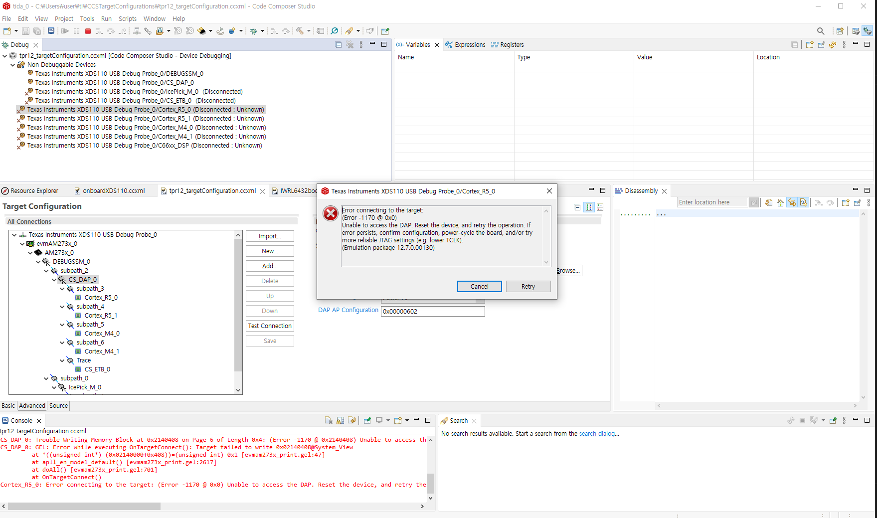
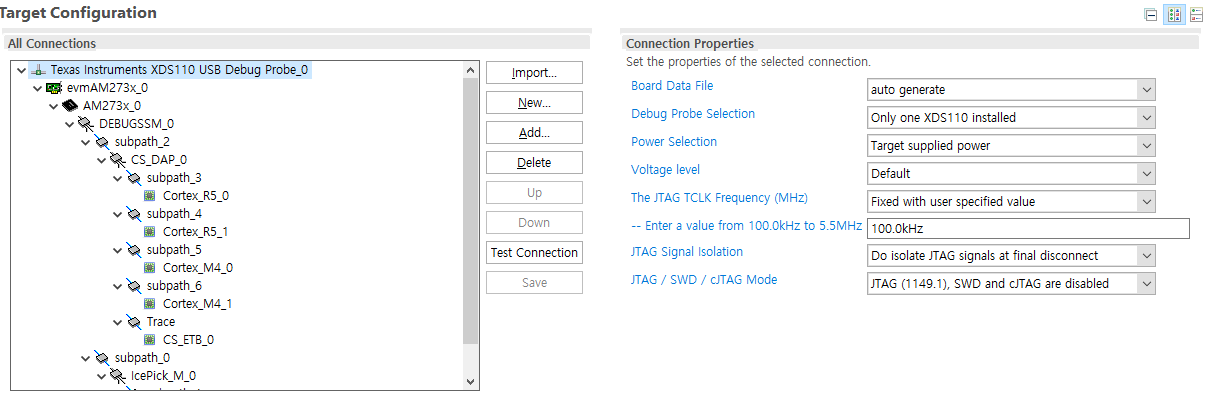
My customer is working on TIDA-0200047 Ref. B/D and faced an issue while trying to download XDS110 FW on TM4C as below.

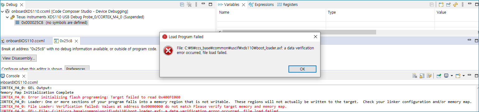
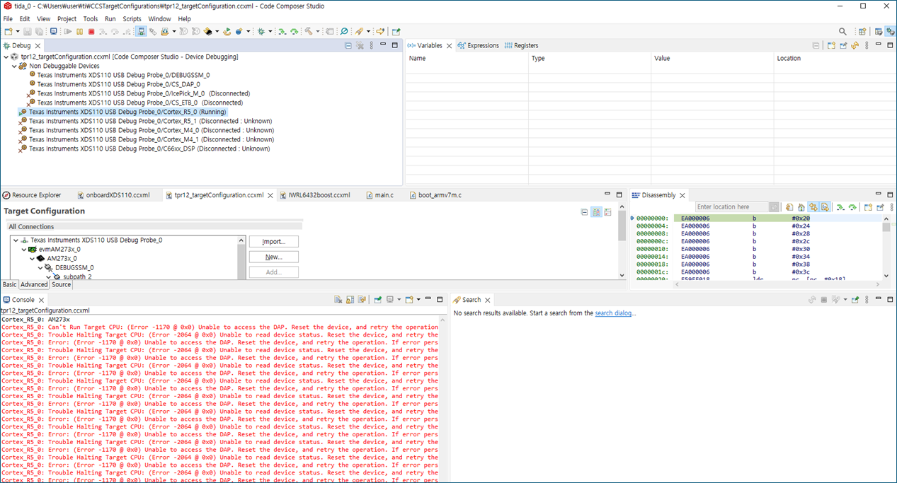
Could you please check why 'initializing flash programming' error occurred in below?

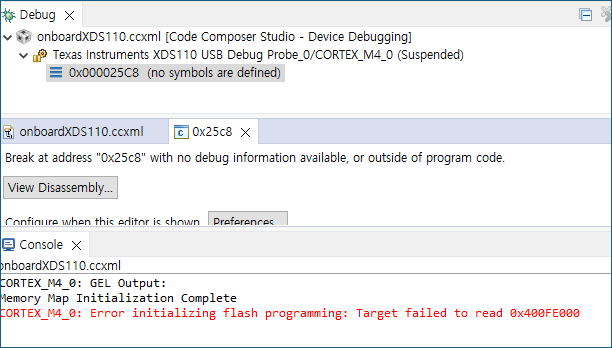
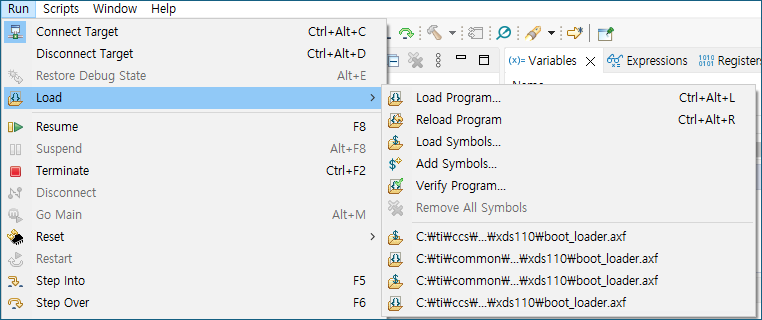
After this, they faced another error in below when they tried to load 'boot_loader.axf' file.

Could you please let me know what is the issue?

Let me explain more details why they faced this errors in TM4C used as XDS110 debugger integrated in TIDA-0200047 Ref. B/D.

At the first time, they found 'Stellaris Device Firmware Upgrade' in the PC device manger window as below when they connected TIDA-0200047 Ref. B/D.

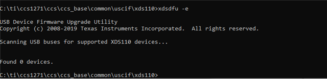
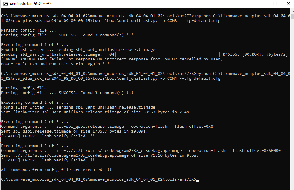
So, they tried to update FW of TM4C using below tool, but they have not seen even above 'Stellaris Device Firmware Upgrade' in their PC device mananger after pressing 'update' in below 'LM Flash Programmer' tool.

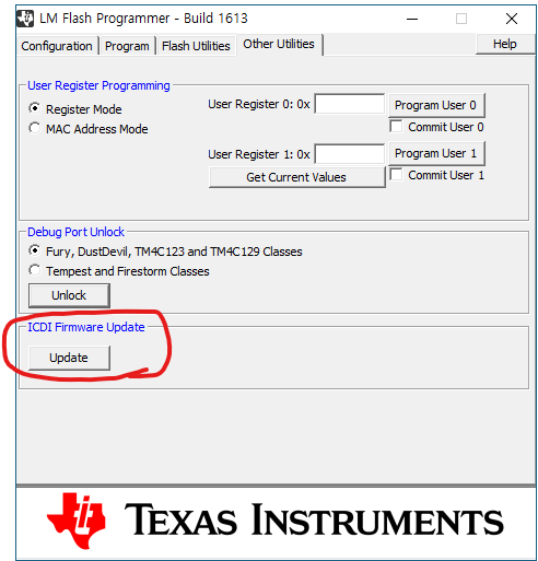
So, there is no way to update XDS110 FW through USB, they tried to connect CCS but failed as above.

Could you please check above errors and how they can update XDS110 FW on XDS110 TM4C?

Thanks and Best Regards,

SI.

  • Hello,

    My customer is working on TIDA-0200047 Ref. B/D

    I assume they have a custom board based on the AWR2243 with an onboard XDS110 designed in based off the TM4C1294NCPDT. Is that correct? If so, can they provide some schematic for the onboard XDS110 on the board?

    Thanks

    ki

  • Hi Ki,

    Yes. you are correct. you can find the schematic in below. It seems JTAG pins are not connected to TM4C and would like to check if there is any other way to flash XDS110 FW on TM4C.

    https://www.ti.com/lit/df/tidmb63/tidmb63.pdf?ts=1729559494799

    https://www.ti.com/tool/TIDA-020047?keyMatch=TIDA-0200047&tisearch=universal_search

    Thanks and Best Regards,

    SI.

  • Yes. you are correct. you can find the schematic in below. It seems JTAG pins are not connected to TM4C and would like to check if there is any other way to flash XDS110 FW on TM4C.

    Based on the screenshots on your original post, it looks like the customer was able to connect to the TM4C using code composer studio but just ran into some flashing issue with trying to flash the XDS110 firmware and bootloader. So I assume they have JTAG access to the TM4C. Can you explain what you mean by JTAG pins are not connected?

  • Hi Ki,

    The JTAG pins are connected to PA0 ~ PA5 of TM4C, but I think the JTAG pins of TM4C are PC0 ~ PC3 in below. (but, I'm not familar with TM4C.. ^^)

    Anyway, if TM4C was connected to CCS but ran into some flashing issue, is there any way to fix it or initialize it?

    When they tried to load FW as below, they failed to load it on TM4C.

    Thanks and Best Regards,

    SI.

  • Anyway, if TM4C was connected to CCS but ran into some flashing issue, is there any way to fix it or initialize it?

    The flash programmer was unable to access the required flash address. I don't know what the root cause of it is.

    The JTAG pins are connected to PA0 ~ PA5 of TM4C, but I think the JTAG pins of TM4C are PC0 ~ PC3 in below. (but, I'm not familar with TM4C.. ^^)

    This is a bit beyond my area of expertise. Hardware support of onboard XDS110 design is provided by the device experts for the device on the board. I will bring it to their attention.

  • Hi Sung,

    Can you check the "Flashing the bootloader" section of the following URL? 

    XDS110 Debug Probe

    Especially the "Option 1: Flash the bootloader from the command-line using the XDSDFU utility".

    Best regards,

    Ming

  • Hi Ming,

    Yes. it was already checked, but connection failed even when they tried to connect GND as below.

    Is there any other method to flash FW?

    Thanks and Best Regards,

    SI.

  • Hi Sung-IL,

    Unfortunately, I do not know any other ways to solve this issue. I will assign this thread to SDTO for further help.

    Best regards,

    Ming 

  • Sung-IL

    I would like to confirm the current situation.

    It looked like in the past the customer was able to detect the XDS110 and start CCS and connect to the Tiva device and the issue was with some programming and verification errors when trying to flash the firmware and bootloader.

    But then after trying to use the LM FLash programmer and use the update feature (which they should not have done since it is for updating ICDI firmware and NOT XDS110 firmware), the XDS110 is no longer detected at all so they can no longer even connect CCS to the Tiva device.

    Is this correct? This is what I need confirmation for.

    If so, I think that by trying to flash the ICDI software, it corrupted the XDS110 software on the device. Looks like the customer tried forcing the device into DFU mode by grounding pin 97 of the Tiva device then connecting the USB cable to the Tiva then disconnecting pin 97 a few seconds afterwards. This is the correct procedure but it looks like in the customer case it did not work. 

  • Hi Ki,

    All your understanding is right.

    Thanks and Best Regards,

    SI.

  • Please see the below screenshot you posted earlier:

    This looks like the customer has JTAG access to the onboard XDS110 Tiva chip using an external XDS110 JTAG probe. This is a direct JTAG access (JTAG header on the board or otherwise) and not using the USB port connect that xdsdfu uses. This would allow you to connect the CCS debugger to it. This step no longer works after the failed ICDI firmware update? What happens when they try to connect the CCS debugger like they did in the screenshot above?

  • Hi Sung-IL,

    I have also noticed from your picture that the header J6 is set to "Flash" mode instead of run, I believe that the jumper has to be switched as well in order to connect the cores to CCS. 

    Out of curiosity, are you still able to flash images via the uniflash tool? is the problem exclusively an issue with connecting to JTAG via CCS? 

    Best,

    Daniel 

  • Hi Daniel,

    Even when they set the header J6 to "RUN" mode, they still failed to connect JTAG as below.

    [Error LOG]

    CS_DAP_0: GEL Output: Connecting Target...

    CS_DAP_0: GEL Output: PLL_CORE_CLK Programmed Frequency = 800   

    CS_DAP_0: GEL Output: PLL_CORE_HSDIVIDER_CLKOUT0 Programmed Frequency = 160   

    CS_DAP_0: GEL Output: PLL_CORE_HSDIVIDER_CLKOUT1 Programmed Frequency = 160   

    CS_DAP_0: GEL Output: PLL_CORE_HSDIVIDER_CLKOUT2 Programmed Frequency = 400   

    CS_DAP_0: GEL Output: PLL_DSP_CLK Programmed Frequency = 14880   

    CS_DAP_0: GEL Output: PLL_DSP_HSDIVIDER_CLKOUT0 Programmed Frequency = 2976   

    CS_DAP_0: GEL Output: PLL_DSP_HSDIVIDER_CLKOUT1 Programmed Frequency = 2976   

    CS_DAP_0: GEL Output: PLL_DSP_HSDIVIDER_CLKOUT2 Programmed Frequency = 2976   

    CS_DAP_0: GEL Output: PLL_PER_CLK Programmed Frequency = 14880   

    CS_DAP_0: GEL Output: PLL_PER_HSDIVIDER_CLKOUT0 Programmed Frequency = 2976   

    CS_DAP_0: GEL Output: PLL_PER_HSDIVIDER_CLKOUT1 Programmed Frequency = 2976   

    CS_DAP_0: GEL Output: PLL_PER_HSDIVIDER_CLKOUT2 Programmed Frequency = 2976   

    CS_DAP_0: GEL Output: doAll1 - pll_clock_detection done

    CS_DAP_0: Trouble Writing Memory Block at 0x2140408 on Page 6 of Length 0x4: (Error -1170 @ 0x2140408) Unable to access the DAP. Reset the device, and retry the operation. If error persists, confirm configuration, power-cycle the board, and/or try more reliable JTAG settings (e.g. lower TCLK). (Emulation package 12.7.0.00130)

    CS_DAP_0: GEL: Error while executing OnTargetConnect(): Target failed to write 0x02140408@System_View

               at *((unsigned int*) (0x02140000+0x408))=(unsigned int) 0x1 [evmam273x_print.gel:47]

               at apll_en_mode1_default() [evmam273x_print.gel:2617]

               at doAll() [evmam273x_print.gel:701]

               at OnTargetConnect()

    Cortex_R5_0: Error connecting to the target: (Error -1170 @ 0x0) Unable to access the DAP. Reset the device, and retry the operation. If error persists, confirm configuration, power-cycle the board, and/or try more reliable JTAG settings (e.g. lower TCLK). (Emulation package 12.7.0.00130)


    Thanks and Best Regards,

    SI.

  • Hi SI,

    The error log above normally indicates a problem when trying to run gel scripts. to get around this I flash the SBL and then launch a target configuration without any gels, and this usually fixes the problem for me. Do you have the mmwave_mcuplus_sdk installed? if not, please download it from here:

    MMWAVE-MCUPLUS-SDK Software development kit (SDK) | TI.com

    I understand that this is a workaround, but you can try the following to see if you can establish a connection via JTAG:

    1. Change the jumper back to "Flash" mode
    2. after installing the above sdk, if not previously done, flash the default.cfg file (C:\ti\mmwave_mcuplus_sdk_04_04_01_02\mmwave_mcuplus_sdk_04_04_01_02\tools\am273x\default.cfg) via uniflash onto the board.
    3. After it's done flashing, switch the jumper back to "Run" and reset the board
    4. at this stage, you should be able to launch a target config with no gels and connect to the cores, assuming there is no other underlying issue
      1. you can ensure the .ccxml does not have gels associated with it by opening it and checking the DAP under the "Advanced" tab. If the "initialization script" box on the right is populated, just delete and save
      2. Also attaching the one I use for convenience:  /cfs-file/__key/communityserver-discussions-components-files/908/am273noGel.ccxml

    Please give this a try and update

    Best,

    Daniel

  • Hi Daniel,

    Thanks to your guidance, they can connect R5 core, but still failed to flash SBL and to load SW on R5 core after connecting.

    How they can flash SBL to initialize device or load GEL?

    They failed to flash image using UART_UNIFLASH as below.

    After this flash failed, they can connect R5 core without GEL file, but failed to load program as below.

    Thanks and Best Regards,

    SI.

  • Hi Sung-IL,

    if you open the device manager, are the User/Application and Data Ports visible in the COM Ports section?

  • Hi Daniel,

    No. those were not seen in COM Ports section of their PC device manager when they connected to the USB type B of the board.

    Thanks and Best Regards,

    SI.

  • Hi Sung-IL,

    In your CCS installation folder under ccs_<version>\ccs\ccs_base\common\uscif\xds110 you can find a document called "XDS110SupportReadMe.pdf." In this document you can find information on how to recover a bricked XD110 on a board without access to JTAG or with a physical JTAG connection. Could you please try running the following steps on your board and see if with this you can fix the issue? 

    You can also find these instructions in the previously mentioned document. Recovering without a JTAG connection might be simpler in this case since you wouldn't need an additional flash tool

    Best,

    Daniel