This thread has been locked.

If you have a related question, please click the "Ask a related question" button in the top right corner. The newly created question will be automatically linked to this question.

LP-MSPM0G3507: WAKEUP from SHUTDOWN mode cannot be performed with PA11 (high-drive pin)

Genius 5870 points
Part Number: LP-MSPM0G3507
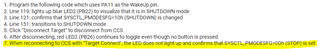
Other Parts Discussed in Thread: MSPM0G3507, SYSCONFIG

Tool/software:

Hi experts,

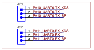
I used "sysctl_shutdown_LP_MSPM0G3507_nortos_ticlang" on LP-MSPM0G3507 and added PA11 to the pin for WAKEUP in Sysconfig.
As a result, WAKEUP events from SHUTDOWN mode seem to occur intermittently.

Q1:I will attach the .c and .syscfg files, so could you point out any settings I missed?

sysctl_shutdown_editPA11.c
/*
 * Copyright (c) 2021, Texas Instruments Incorporated
 * All rights reserved.
 *
 * Redistribution and use in source and binary forms, with or without
 * modification, are permitted provided that the following conditions
 * are met:
 *
 * *  Redistributions of source code must retain the above copyright
 *    notice, this list of conditions and the following disclaimer.
 *
 * *  Redistributions in binary form must reproduce the above copyright
 *    notice, this list of conditions and the following disclaimer in the
 *    documentation and/or other materials provided with the distribution.
 *
 * *  Neither the name of Texas Instruments Incorporated nor the names of
 *    its contributors may be used to endorse or promote products derived
 *    from this software without specific prior written permission.
 *
 * THIS SOFTWARE IS PROVIDED BY THE COPYRIGHT HOLDERS AND CONTRIBUTORS "AS IS"
 * AND ANY EXPRESS OR IMPLIED WARRANTIES, INCLUDING, BUT NOT LIMITED TO,
 * THE IMPLIED WARRANTIES OF MERCHANTABILITY AND FITNESS FOR A PARTICULAR
 * PURPOSE ARE DISCLAIMED. IN NO EVENT SHALL THE COPYRIGHT OWNER OR
 * CONTRIBUTORS BE LIABLE FOR ANY DIRECT, INDIRECT, INCIDENTAL, SPECIAL,
 * EXEMPLARY, OR CONSEQUENTIAL DAMAGES (INCLUDING, BUT NOT LIMITED TO,
 * PROCUREMENT OF SUBSTITUTE GOODS OR SERVICES; LOSS OF USE, DATA, OR PROFITS;
 * OR BUSINESS INTERRUPTION) HOWEVER CAUSED AND ON ANY THEORY OF LIABILITY,
 * WHETHER IN CONTRACT, STRICT LIABILITY, OR TORT (INCLUDING NEGLIGENCE OR
 * OTHERWISE) ARISING IN ANY WAY OUT OF THE USE OF THIS SOFTWARE,
 * EVEN IF ADVISED OF THE POSSIBILITY OF SUCH DAMAGE.
 */

#include "ti_msp_dl_config.h"

int main(void)
{
    volatile DL_SYSCTL_RESET_CAUSE rstCause;
    uint8_t counter;
    uint8_t blink;

    /*
     * Initialize GPIOs after reset, or re-initialize after waking-up from
     * SHUTDOWN.
     *
     * GPIOs will retain their last state prior to entry into SHUTDOWN and
     * they need to be re-configured before releasing them by calling
     * DL_SYSCTL_enableShutdownIORelease
     */
    SYSCFG_DL_init();

    rstCause = DL_SYSCTL_getResetCause();

    if (DL_SYSCTL_RESET_CAUSE_BOR_WAKE_FROM_SHUTDOWN == rstCause)
    /* Device was woken up from a SHUTDOWN state from this GPIO pin */
    {
        /* Release IO after Shutdown before initializing any peripherals */
        SYSCFG_DL_GPIO_init();
        DL_SYSCTL_releaseShutdownIO();
        DL_GPIO_disableWakeUp(GPIO_SWITCH_USER_SWITCH_1_IOMUX);
        //add
        DL_GPIO_disableWakeUp(GPIO_SWITCH_USER_SWITCH_2_IOMUX);
        DL_GPIO_disableWakeUp(GPIO_SWITCH_USER_SWITCH_3_IOMUX);
//        DL_GPIO_disableWakeUp(GPIO_SWITCH_USER_SWITCH_4_IOMUX);
        //

        /* Load save state after wake from SHUTDNSTORE */
        counter = 1 + DL_SYSCTL_getShutdownStorageByte(
                          DL_SYSCTL_SHUTDOWN_STORAGE_BYTE_0);

        /* Blink LED a number of times equal to counter */
        for (blink = 0; blink < (2 * counter); blink++) {
            DL_GPIO_togglePins(GPIO_LEDS_PORT, GPIO_LEDS_USER_LED_2_PIN);
            delay_cycles(16000000);
        }
    } else
    /* Device was NOT woken up from a SHUTDOWN state from this GPIO pin */
    {
        counter = 0;
        DL_GPIO_setPins(GPIO_LEDS_PORT, GPIO_LEDS_USER_LED_1_PIN);
        delay_cycles(200000);
        DL_GPIO_clearPins(GPIO_LEDS_PORT, GPIO_LEDS_USER_LED_1_PIN);
    }

    /**
     * Resolve which Power policy to enable based on GPIO_INPUT_CONFIG_0_PIN and
     * GPIO_INPUT_CONFIG_1_PIN state.
     */
    switch (DL_GPIO_readPins(GPIO_INPUT_PORT,
        (GPIO_INPUT_CONFIG_0_PIN | GPIO_INPUT_CONFIG_1_PIN))) {
        /**
         * GPIO_INPUT_CONFIG_0_PIN and GPIO_INPUT_CONFIG_1_PIN are not connected
         * (since inputs are internally pulled high the pins will be at Vcc).
         */
        case (GPIO_INPUT_CONFIG_0_PIN | GPIO_INPUT_CONFIG_1_PIN):
            /**
             * Configure Shutdown wake-up pin to wake-up when pin is set
             * to high before changing power policy to SHUTDOWN
             */
            DL_GPIO_initDigitalInputFeatures(GPIO_SWITCH_USER_SWITCH_1_IOMUX,
                DL_GPIO_INVERSION_DISABLE, DL_GPIO_RESISTOR_NONE,
                DL_GPIO_HYSTERESIS_DISABLE, DL_GPIO_WAKEUP_ON_1);
            //add
            DL_GPIO_initDigitalInputFeatures(GPIO_SWITCH_USER_SWITCH_2_IOMUX,
                DL_GPIO_INVERSION_DISABLE, DL_GPIO_RESISTOR_NONE,
                DL_GPIO_HYSTERESIS_DISABLE, DL_GPIO_WAKEUP_ON_1);
            DL_GPIO_initDigitalInputFeatures(GPIO_SWITCH_USER_SWITCH_3_IOMUX,
                DL_GPIO_INVERSION_DISABLE, DL_GPIO_RESISTOR_NONE,
                DL_GPIO_HYSTERESIS_DISABLE, DL_GPIO_WAKEUP_ON_1);
//            DL_GPIO_initDigitalInputFeatures(GPIO_SWITCH_USER_SWITCH_4_IOMUX,
//                DL_GPIO_INVERSION_DISABLE, DL_GPIO_RESISTOR_NONE,
//                DL_GPIO_HYSTERESIS_DISABLE, DL_GPIO_WAKEUP_ON_1);
            //

            DL_SYSCTL_setPowerPolicySHUTDOWN();
            break;
        /**
         *  GPIO_INPUT_CONFIG_0_PIN  is not connected and
         *  GPIO_INPUT_CONFIG_1_PIN is connected to ground.
         */
        case (GPIO_INPUT_CONFIG_0_PIN):
            DL_SYSCTL_setPowerPolicySTOP0();
            break;
        /**
         *  GPIO_INPUT_CONFIG_0_PIN is connected to ground and
         *  GPIO_INPUT_CONFIG_1_PIN is not connected.
         */
        case (GPIO_INPUT_CONFIG_1_PIN):
            DL_SYSCTL_setPowerPolicySTANDBY0();
            break;
        /**
         * GPIO_INPUT_CONFIG_0_PIN and GPIO_INPUT_CONFIG_1_PIN are connected to
         * ground
         */
        default:
            DL_SYSCTL_setPowerPolicyRUN0SLEEP0();
            break;
    }

    /* Save application state before shutdown using SHUTDNSTORE */
    DL_SYSCTL_setShutdownStorageByte(
        DL_SYSCTL_SHUTDOWN_STORAGE_BYTE_0, counter);

    while (1) {
        __WFI(); /* Enter selected power policy */
    }
}

sysctl_shutdown_editPA11.syscfg.txt
/**
 * These arguments were used when this file was generated. They will be automatically applied on subsequent loads
 * via the GUI or CLI. Run CLI with '--help' for additional information on how to override these arguments.
 * @cliArgs --device "MSPM0G350X" --part "Default" --package "LQFP-64(PM)" --product "mspm0_sdk@2.01.00.03"
 * @v2CliArgs --device "MSPM0G3507" --package "LQFP-64(PM)" --product "mspm0_sdk@2.01.00.03"
 * @versions {"tool":"1.21.2+3837"}
 */

/**
 * Import the modules used in this configuration.
 */
const Board  = scripting.addModule("/ti/driverlib/Board");
const GPIO   = scripting.addModule("/ti/driverlib/GPIO", {}, false);
const GPIO1  = GPIO.addInstance();
const GPIO2  = GPIO.addInstance();
const GPIO3  = GPIO.addInstance();
const SYSCTL = scripting.addModule("/ti/driverlib/SYSCTL");

/**
 * Write custom configuration values to the imported modules.
 */
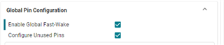
Board.configureUnused  = true;
Board.globalFastWakeEn = true;

GPIO1.$name                         = "GPIO_LEDS";
GPIO1.port                          = "PORTB";
GPIO1.associatedPins.create(2);
GPIO1.associatedPins[0].$name       = "USER_LED_1";
GPIO1.associatedPins[0].assignedPin = "22";
GPIO1.associatedPins[0].pin.$assign = "PB22";
GPIO1.associatedPins[1].$name       = "USER_LED_2";
GPIO1.associatedPins[1].assignedPin = "26";
GPIO1.associatedPins[1].pin.$assign = "PB26";

GPIO2.$name                         = "GPIO_SWITCH";
GPIO2.port                          = "PORTA";
GPIO2.associatedPins.create(3);
GPIO2.associatedPins[0].direction   = "INPUT";
GPIO2.associatedPins[0].$name       = "USER_SWITCH_1";
GPIO2.associatedPins[0].polarity    = "RISE";
GPIO2.associatedPins[0].wakeupLogic = "ON_1";
GPIO2.associatedPins[0].assignedPin = "18";
GPIO2.associatedPins[0].pin.$assign = "PA18";
GPIO2.associatedPins[1].$name       = "USER_SWITCH_2";
GPIO2.associatedPins[1].direction   = "INPUT";
GPIO2.associatedPins[1].assignedPin = "17";
GPIO2.associatedPins[1].wakeupLogic = "ON_1";
GPIO2.associatedPins[1].polarity    = "RISE";
GPIO2.associatedPins[1].pin.$assign = "PA17";
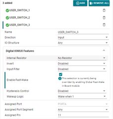
GPIO2.associatedPins[2].$name       = "USER_SWITCH_3";
GPIO2.associatedPins[2].direction   = "INPUT";
GPIO2.associatedPins[2].assignedPin = "11";
GPIO2.associatedPins[2].wakeupLogic = "ON_1";
GPIO2.associatedPins[2].polarity    = "RISE";
GPIO2.associatedPins[2].fastWakeEn  = true;
GPIO2.associatedPins[2].pin.$assign = "PA11";

GPIO3.$name                              = "GPIO_INPUT";
GPIO3.port                               = "PORTB";
GPIO3.associatedPins.create(2);
GPIO3.associatedPins[0].$name            = "CONFIG_0";
GPIO3.associatedPins[0].direction        = "INPUT";
GPIO3.associatedPins[0].internalResistor = "PULL_UP";
GPIO3.associatedPins[0].assignedPin      = "17";
GPIO3.associatedPins[1].$name            = "CONFIG_1";
GPIO3.associatedPins[1].assignedPin      = "12";
GPIO3.associatedPins[1].direction        = "INPUT";
GPIO3.associatedPins[1].internalResistor = "PULL_UP";

SYSCTL.forceDefaultClkConfig = true;
SYSCTL.clockTreeEn           = true;

/**
 * Pinmux solution for unlocked pins/peripherals. This ensures that minor changes to the automatic solver in a future
 * version of the tool will not impact the pinmux you originally saw.  These lines can be completely deleted in order to
 * re-solve from scratch.
 */
Board.peripheral.$suggestSolution            = "DEBUGSS";
Board.peripheral.swclkPin.$suggestSolution   = "PA20";
Board.peripheral.swdioPin.$suggestSolution   = "PA19";
GPIO3.associatedPins[0].pin.$suggestSolution = "PB17";
GPIO3.associatedPins[1].pin.$suggestSolution = "PB12";

I checked and configured TRM "8.2.4 SHUTDOWN Mode Wakeup Logic" and "9.2.4 GPIO Fast Wake".
I have problems using high-drive pins such as PA31.
My customer's application requires a minimum of 4 inputs to detect WakeUp and start-up factors. It seems that open-drain ports can also be used, but these are being used for other purposes.


Best regards,
O.H

  • Hi, thanks for the question! Let me pull your contents into a new project on my end and see if I can see what is missing.

    -Brian

  • Hi, Just wanted to follow up and let you know I am still looking into this. I am able to replicate the issue you are having and I am looking for a possible solution and reason for the behavior to provide you. I will keep you updated on the progress.

    -Brian

  • Hi Brain,

    I understood your situation. Thank you for your supports.

    Best Regards,
    O.H

  • Hi Brain,

    I have performed additional experiments, but I have some additional questions.

    Q2: I cannot use the break point "sysctl_shutdown_LP_MSPM0G3507_nortos_ticlang", is there a solution?
    Even with the sample code in an unmodified state, when connected with CCS, pressing SW1 (PA18) does not toggle red LED2 (PB26).

    Q3: As shown folowing, SYSCTL_PMODESFG changes automatically from 10h (SHUTDOWN) to 00h (STOP).
    Could you tell me what the possible causes are?

    1. Program the following code which uses PA11 as the WakeUp pin.
    2. Line 119: lights up blue LED2 (PB22) to visualize that it is in SHUTDOWN mode
    3. Line 121: confirms that SYSCTL_PMODESFG=10h (SHUTDOWN) is changed
    4. Line 151: transitions to SHUTDOWN mode
    5. Click "Disconnect Target" to disconnect from CCS
    6. After disconnecting, red LED2 (PB26) continues to toggle even though no button is pressed.
    7. When reconnecting to CCS with "Target Connect", the LED does not light up and confirms that SYSCTL_PMODESFG=00h (STOP) is set

    sysctl_shutdown_editPA11_ver2.c
    /*
     * Copyright (c) 2021, Texas Instruments Incorporated
     * All rights reserved.
     *
     * Redistribution and use in source and binary forms, with or without
     * modification, are permitted provided that the following conditions
     * are met:
     *
     * *  Redistributions of source code must retain the above copyright
     *    notice, this list of conditions and the following disclaimer.
     *
     * *  Redistributions in binary form must reproduce the above copyright
     *    notice, this list of conditions and the following disclaimer in the
     *    documentation and/or other materials provided with the distribution.
     *
     * *  Neither the name of Texas Instruments Incorporated nor the names of
     *    its contributors may be used to endorse or promote products derived
     *    from this software without specific prior written permission.
     *
     * THIS SOFTWARE IS PROVIDED BY THE COPYRIGHT HOLDERS AND CONTRIBUTORS "AS IS"
     * AND ANY EXPRESS OR IMPLIED WARRANTIES, INCLUDING, BUT NOT LIMITED TO,
     * THE IMPLIED WARRANTIES OF MERCHANTABILITY AND FITNESS FOR A PARTICULAR
     * PURPOSE ARE DISCLAIMED. IN NO EVENT SHALL THE COPYRIGHT OWNER OR
     * CONTRIBUTORS BE LIABLE FOR ANY DIRECT, INDIRECT, INCIDENTAL, SPECIAL,
     * EXEMPLARY, OR CONSEQUENTIAL DAMAGES (INCLUDING, BUT NOT LIMITED TO,
     * PROCUREMENT OF SUBSTITUTE GOODS OR SERVICES; LOSS OF USE, DATA, OR PROFITS;
     * OR BUSINESS INTERRUPTION) HOWEVER CAUSED AND ON ANY THEORY OF LIABILITY,
     * WHETHER IN CONTRACT, STRICT LIABILITY, OR TORT (INCLUDING NEGLIGENCE OR
     * OTHERWISE) ARISING IN ANY WAY OUT OF THE USE OF THIS SOFTWARE,
     * EVEN IF ADVISED OF THE POSSIBILITY OF SUCH DAMAGE.
     */
    
    #include "ti_msp_dl_config.h"
    
    int main(void)
    {
        volatile DL_SYSCTL_RESET_CAUSE rstCause;
        uint8_t counter;
        uint8_t blink;
    
        /*
         * Initialize GPIOs after reset, or re-initialize after waking-up from
         * SHUTDOWN.
         *
         * GPIOs will retain their last state prior to entry into SHUTDOWN and
         * they need to be re-configured before releasing them by calling
         * DL_SYSCTL_enableShutdownIORelease
         */
        SYSCFG_DL_init();
    
        rstCause = DL_SYSCTL_getResetCause();
        //add
        DL_GPIO_clearPins(GPIO_LEDS_PORT, GPIO_LEDS_USER_LED_1_PIN);
        //
    
        if (DL_SYSCTL_RESET_CAUSE_BOR_WAKE_FROM_SHUTDOWN == rstCause)
        /* Device was woken up from a SHUTDOWN state from this GPIO pin */
        {
            /* Release IO after Shutdown before initializing any peripherals */
            SYSCFG_DL_GPIO_init();
    
            DL_SYSCTL_releaseShutdownIO();
            DL_GPIO_disableWakeUp(GPIO_SWITCH_USER_SWITCH_1_IOMUX);
            //add
            DL_GPIO_disableWakeUp(GPIO_SWITCH_USER_SWITCH_2_IOMUX);
            DL_GPIO_disableWakeUp(GPIO_SWITCH_USER_SWITCH_3_IOMUX);
    //        DL_GPIO_disableWakeUp(GPIO_SWITCH_USER_SWITCH_4_IOMUX);
            //
    
            /* Load save state after wake from SHUTDNSTORE */
            counter = 1 + DL_SYSCTL_getShutdownStorageByte(
                              DL_SYSCTL_SHUTDOWN_STORAGE_BYTE_0);
    
            /* Blink LED a number of times equal to counter */
            for (blink = 0; blink < (2 * counter); blink++) {
                DL_GPIO_togglePins(GPIO_LEDS_PORT, GPIO_LEDS_USER_LED_2_PIN);
                delay_cycles(16000000);
            }
        } else
        /* Device was NOT woken up from a SHUTDOWN state from this GPIO pin */
        {
            counter = 0;
            DL_GPIO_setPins(GPIO_LEDS_PORT, GPIO_LEDS_USER_LED_1_PIN);
            delay_cycles(200000);
            DL_GPIO_clearPins(GPIO_LEDS_PORT, GPIO_LEDS_USER_LED_1_PIN);
        }
    
        /**
         * Resolve which Power policy to enable based on GPIO_INPUT_CONFIG_0_PIN and
         * GPIO_INPUT_CONFIG_1_PIN state.
         */
        switch (DL_GPIO_readPins(GPIO_INPUT_PORT,
            (GPIO_INPUT_CONFIG_0_PIN | GPIO_INPUT_CONFIG_1_PIN))) {
            /**
             * GPIO_INPUT_CONFIG_0_PIN and GPIO_INPUT_CONFIG_1_PIN are not connected
             * (since inputs are internally pulled high the pins will be at Vcc).
             */
            case (GPIO_INPUT_CONFIG_0_PIN | GPIO_INPUT_CONFIG_1_PIN):
                /**
                 * Configure Shutdown wake-up pin to wake-up when pin is set
                 * to high before changing power policy to SHUTDOWN
                 */
                DL_GPIO_initDigitalInputFeatures(GPIO_SWITCH_USER_SWITCH_1_IOMUX,
                    DL_GPIO_INVERSION_DISABLE, DL_GPIO_RESISTOR_NONE,
                    DL_GPIO_HYSTERESIS_DISABLE, DL_GPIO_WAKEUP_ON_1);
                //add
                DL_GPIO_initDigitalInputFeatures(GPIO_SWITCH_USER_SWITCH_2_IOMUX,
                    DL_GPIO_INVERSION_DISABLE, DL_GPIO_RESISTOR_NONE,
                    DL_GPIO_HYSTERESIS_DISABLE, DL_GPIO_WAKEUP_ON_1);
                DL_GPIO_initDigitalInputFeatures(GPIO_SWITCH_USER_SWITCH_3_IOMUX,
                    DL_GPIO_INVERSION_DISABLE, DL_GPIO_RESISTOR_NONE,
                    DL_GPIO_HYSTERESIS_DISABLE, DL_GPIO_WAKEUP_ON_1);
    //            DL_GPIO_initDigitalInputFeatures(GPIO_SWITCH_USER_SWITCH_4_IOMUX,
    //                DL_GPIO_INVERSION_DISABLE, DL_GPIO_RESISTOR_NONE,
    //                DL_GPIO_HYSTERESIS_DISABLE, DL_GPIO_WAKEUP_ON_1);
                //
    
                //add
                DL_GPIO_setPins(GPIO_LEDS_PORT, GPIO_LEDS_USER_LED_1_PIN);
                //
                DL_SYSCTL_setPowerPolicySHUTDOWN();
                break;
            /**
             *  GPIO_INPUT_CONFIG_0_PIN  is not connected and
             *  GPIO_INPUT_CONFIG_1_PIN is connected to ground.
             */
            case (GPIO_INPUT_CONFIG_0_PIN):
                DL_SYSCTL_setPowerPolicySTOP0();
                break;
            /**
             *  GPIO_INPUT_CONFIG_0_PIN is connected to ground and
             *  GPIO_INPUT_CONFIG_1_PIN is not connected.
             */
            case (GPIO_INPUT_CONFIG_1_PIN):
                DL_SYSCTL_setPowerPolicySTANDBY0();
                break;
            /**
             * GPIO_INPUT_CONFIG_0_PIN and GPIO_INPUT_CONFIG_1_PIN are connected to
             * ground
             */
            default:
                DL_SYSCTL_setPowerPolicyRUN0SLEEP0();
                break;
        }
    
        /* Save application state before shutdown using SHUTDNSTORE */
        DL_SYSCTL_setShutdownStorageByte(
            DL_SYSCTL_SHUTDOWN_STORAGE_BYTE_0, counter);
    
        while (1) {
            __WFI(); /* Enter selected power policy */
        }
    }
    

    Best regards,
    O.H

  • Hi Brain,

    I apologize.
    I was able to recover from SHUTDOWN state using PA11 and PA31, so there is no need to answer the first Q1.

    Q:I will attach the .c and .syscfg files, so could you point out any settings I missed?

    As for PA11, the pins were floating because J21 and J22 were disconnected. It seems that wakeups were occurring constantly due to this unstable state.
    If you fix PA11 and PA31 to GND, they will maintain SHUTDOWN mode, and if you connect them to 3V3 (or the J8 switch), they will wake up normally.
    By the way, it seems that checking "Enable FAST-WAKE" in the Global and GPIO settings in Sysconfig is not relevant.

    However, Q2 and Q3 remain unchanged, so please answer them.

    Best regards,
    O.H

  • Hi O.H. for your second question can you clarify what you mean by not being able to use the breakpoint? For your third question, what do you have your config pins set to? Do you also have the SLEEPDEEP bit set as well before entering shutdown mode?

  • Hi Brain,

    For your third question, what do you have your config pins set to? Do you also have the SLEEPDEEP bit set as well before entering shutdown mode?

    I'm sorry. I was able to solve Q3 myself after solving Q1.


    When I reconnected to CCS, a Debug Reset of the device occurred, and I understand that it stopped before passing line 121. After that, I was able to confirm that it passed line 121 with Step Over and became SYSCTL_PMODESFG=10h (SHUTDOWN).

    for your second question can you clarify what you mean by not being able to use the breakpoint?

    If it is done immediately after writing the program, you can confirm that it stops at the specified BreakPoint. However, once you execute __WFI() on line 151, it does not stop at the BreakPoint.
    Therefore, I am unable to track the behavior of the program after WakeUp.

    Best regards,
    O.H

  • Maybe this could be due to the debug reset as well? I am not sure that the breakpoints maintain after a device has disconnected and then reconnected.

  • Hi Brain,

    I am not sure that the breakpoints maintain after a device has disconnected and then reconnected.

    Regardless of reconnection,
    set a BreakPoint on line 12 → When executed, it stops at line 121 → Execute __WFI() with Step Over → Press "Run" and press SW1 → LED2 does not light up, and it does not stop at the BreakPoint on line 121 = WakeUp debugging cannot be confirmed.

    Best regards,
    O.H