This thread has been locked.

If you have a related question, please click the "Ask a related question" button in the top right corner. The newly created question will be automatically linked to this question.

TM4C123FH6PM Locked

Other Parts Discussed in Thread: TM4C123FH6PM

Hi,


We bought Stellaris one EKI-LM4F232 Eval Kit and we've been programing it without problem.

Now we are assembling our own board using TM4C123FH6PM. We didn´t have any problems until I changed my code, then I can't download anymore.

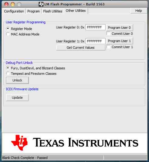
I think it is locked up. I read in your pages that we can unlock the processor using LM Flash Programmer plus EKI-LM4F232. But I didn´t find any documentation that shows how I can do that. 

Can anyone help me?

  • Jose,

    Please plug the board in and goto the "Other Utilities" tab, see below.  

    Change the radio button to the Blizzard Class option, and then click the "Unlock" button.  The tool will walk you through the rest of the process.

    Regards,
    Chris

  • Hi Chris,

    I'm sorry. The problem isn't in the Eval Kit, it's been working fine. The problem is in our own dev board.
    It has only a 10 pin JTAG conector. We've been trying to connect by using ULINK-ME from Keil without success.
    I am asking your help to connect the Eval Kit in my dev board to unlock its processor (TM4C123FH6PM) .

    Best regards,

    José Fernando

  • Jose,

    Thanks for clarifying, i have a few more questions:

    1) Can you send me the symbolization that is on the package for the TM4C123 device you have populated on your board?

    2) Are you repurposing the JTAG pins within your code for some other functionality?  Or is it your intent to always leave them as JTAG debug port access?  Can you share the code snippets you added which you think corrupted the device?

    3) Are you using the EEPROM within your application?

    4) Can you share the relavent schematic pages showing how you have the JTAG pins connected?

    Regards,
    Chris

  • Hi Chris,

    these are my answers:

    1) Package symbolization printed on the chip is:
    * 980 YF
    * TM4C123F
    * H6PMI
    * 35AKQEW
    * G4

    2) We don't intend to use JTAG pins to other function. My code was very simple. The problem appeared after I tried to access hardware I/O. The previous program was  a very simple counting loop.int

    main(void)
    {
      int i=1;

      SysCtlPeripheralEnable(SYSCTL_PERIPH_GPIOF);

      GPIOPinTypeGPIOOutput(GPIO_PORTF_BASE, GPIO_PIN_3 );

      while(i)
      {
        GPIOPinWrite(GPIO_PORTF_BASE, GPIO_PIN_3, 0XFF);
        SysCtlDelay(1000 );

        GPIOPinWrite(GPIO_PORTF_BASE, GPIO_PIN_3, 0X0);
        SysCtlDelay(1000 );
      }

      return 0;
    }

    3)No.

    4) I Attached the file "Circuit.png". As you can see, we assembled the minimal components besides power supply; JTAG ; VDD capacitors; RC for reset.

    Best regards,

    José Fernando

  • Jose,

    If you are just trying to toggle PF3, i think the while loop should be as follows:

      while(i)
      {
        GPIOPinWrite(GPIO_PORTF_BASE, GPIO_PIN_3, 0X8);
        SysCtlDelay(1000 );

        GPIOPinWrite(GPIO_PORTF_BASE, GPIO_PIN_3, 0X0);
        SysCtlDelay(1000 );
      }

    ...but i don't think this is the root of your problem.

    On your VDDC net you have a single 3.3uF which should be ok but also placement and ESR of the cap is important. Can you share these details. These care-abouts are explained with the Tiva C Series System Design Guide

    I also see +3.3VA and +3.3V are separate rails and GND and GNDA are separate. What is the power sequencing for these? Are they connected together somewhere outside of this page? If so, how?  Depending on how these are connected I could see this being a source of a problem.

    In order to try the unlock sequence by jumping from the EK-LM4F232, please try the following:

    1) Populate the 4 JTAG headers shown in the red box below (TDI, TDO, TCK, TMS), and jumper wire these over to the corresponding JTAG pins on the 10-pin connector of your target board.

    2) Press and hold the RESET button shown in the blue circle below.  This keeps the MCU on the EK in reset and should allow the LMFlash application to execute the unlock sequence on your target board.

    3) Run the unlock sequence from LMFLash while holding the EK in reset.

    Regards,
    Chris

    P.S. - I have not tried this locally, but theoretically it should work.  If this is unsuccessful, you may need to try an replace the device on your target board.

  • "GPIOPinWrite(GPIO_PORTF_BASE, GPIO_PIN_3, 0X8);"

    Parameter 2 (above) "GPIO_PIN_3" - serves as a mask - enables 0xFF to only impact PF3.

    While you report "one time working" - schematic shows no vital xtal nor xtal bypass caps (mounted close in to pins 40,41) - so often required - yet nowhere visible...

  • Hi Chris,

    After taking a while, we finally got unlock the processor.
    Besides the four Jtag signals (TMS, TCK, TDI and TDO), we have connected the 3.3V VCC and GND. And we mounted a reset button in our board to keep the RST in low level during the process. We only released after power be on, at the end.
    The mistake I did in my code, I forgot to inform you, is that we have selected external clock without mounted it in our board - using the SysCtlClockSet function in the wrong way.
    Thank you for having supported us!