This thread has been locked.

If you have a related question, please click the "Ask a related question" button in the top right corner. The newly created question will be automatically linked to this question.

Custom board with tm4c123gh6pm, lm flash can't find a targed

Other Parts Discussed in Thread: TPS61024, TM4C123GH6PM

Hi,

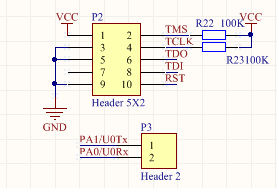
I made custom PCB with Tiva. I've got Jtag connections on board. I've checked all connections between tiva and goldpins and are ok. I'm trying to program tiva using launchpad througth lm flash, and i occure error - unable to find target or unable to initialize the device. I attached some part of scheme. I'm using cristal 7M-16.000MEEQ-T with 10pF decoupling capacitors. Please check my scheme because i dont know what's wrong.
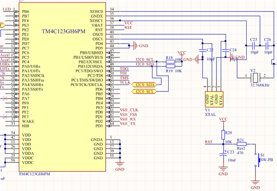
  • Your 2 external pull-up Rs look high in value to me (10K more standard) and no such R appears @ TDI/TDO...

    Have you thoroughly checked each/every Vdd & Vss pin for proper connection?  No bypass C's are shown - many should be in use.  Vddc may require special handling/termination.  Have you complied w/MCU manual?  Is (usual) cap present/proper?

    3V3 regulator makes no appearance - is it tested/verified & appropriate?

    Making just one such board is not our method.  (building 3-5 enables, A-B-C style of testing - preferable to "only board in the world" testing...)

  • Hi,

    normally I use TMS, TDO and TDI pulled up and TCLK pulled down. And it works with LM3Sxxx and TM4C123GH6xx.

    /Michael

  • Indeed - that scheme is recommended by another ARM vendor. 

    We've long moved to SWD (as has that vendor) which is bi-di data & clock - and use pull-ups exclusively (those 2 pins) - with great success...

    As poster's board is homebrew - and perhaps alone - all suspects remain under suspicion...  Making so simple a board - when tested factory ones are available sub 20 (USD) - makes sense... (some where/how one hopes...)

  • hello,

    thank you for your fast anwer an apalogise me for not posting all scheme. Yes there are coupling capacitors one per VDD pin and 2 cap per VDDC pins. Board is supplied by tps61024 regulator (3V), and also it can be powered form launchpad during programming bypassing tps in this process. I will add resistor as you mentioned, and change value to 10K, and let you know what's going on. Regards to TCLK JTAG PIN, it's no nessesery to use pull up resistor, i've found in datasheet that it's internally pulled up, i hope that i'm not wrong.

  • Hello MatthewFirst,

    Couple of checks you may want to do

    1. Is the VDD and VDDC at the correct voltages of 3.0V and 1.2V

    2. Is the RST Pin at 3.0V level

    3. Get the 4 JTAG's and RST on the scope and when you try to connect do you see TCK, TMS and TDI toggling. If yes, does the TDO toggle.

    There is an internal Pull Up but this is weak pull. Also what debugger are you using, cause sometimes the header of the debugger and pin out may have been swapped (once one of my vendors did that)?

    Regards

    Amit

  • Hello,


    Yes, the voltage is correct. Reset PIN is at 2.84V.  i will check jtag signal.

    i'm using tiva tmc123g launchpad as debugger

  • hello,

    all lines are high. I can't see clock on tclk, and other lines are not toggling too.;/

    error which i got is unable to initialize target -0!

    when i try to program it i got unable to find target.

  • Hello Matthew,

    Reset at 2.84V is not a good sign. It should be more in the proximity of 3.3V. You may want to investigate with a stronger pull up.

    Did you check that the header on the board and the emulator have correct pin mapped. In other words right side mapped to left and vice-versa (I had a board recently where we found the issue to be the wrong header mount of left to right)

    Regards

    Amit

  • Thank you for answer. I think the problem in somę way is solved. In ti wiki about icdi there is recommended to keep ext line low. Suddenly I disconnected this line and left it floating, and after that I was able to program and debug my board. Previously when I was programming this board I've keep ext line low. Do you have for me any recommendations despite of decreasing reset resistor?

  • Pardon - if I may "jump in" quickly/briefly - we've long used 10K for Rst pull-up - many ARM MCUs - many years - unless a severe noise environment - that will work.

    But 2V8 - as Amit states - signals something amiss!  Suggest that you employ proper DMM - measure resistance from Rst to ground - and report.  And - that Rst cap may be suspect - or anything else attached - that pin.  Also check that Rst pull-up "truly" makes it to "stiff" 3V3 source...

  • Hello Matthew,

    The reset line "must not" be low. It should be high. A 10K resistor is OK. There must be another source on the board which is actually pulling the line low with slightly higher strength causing it in a zone were a small glitch on reset line during programming is "killing" the download.

    Suggestion would be to use 1K resistor (as a crude jump start). However w/o knowing what is pulling the reset line low, it would be a futile temporary relief.

    Regards

    Amit

  • Hi,


    resistance between ground and RST is 47,5K.

    ok thank you for your advices, i will dissamsembly rst line and setup again.

    Can you tell me how is that possible to program extrernal chip when EXT pin in ICDI is floating, and connecting this pin low occure an error - unable to initialize/

    ----------------------

    update - normally RST line is 3,27 when icdi is rst pin is not connected to the rst line. When it is, voltage on rst pin is 2V87.

  • Hello Matthew

    The math surely comes close. 3.3V*(47.5K/10K+47.5K) = 2.72V which is close to what you have measured.

    What is the EXT pin you mentioned?

    Regards

    Amit

  • EXT-DBG pin on launchpad http://processors.wiki.ti.com/index.php/Stellaris_LM4F120_LaunchPad_Debug_How_To

  • Hello Matthew,

    So the external debugger is not a XDS or any standard off the shelf debugger but you are using an ICDI from another Stellaris Board as the debugger?

    I am trying to put the pieces together to understand how you have connected the debugger!!!

    Regards

    Amit

  • Yes, i;m using stellaris/tiva launchpad ICDI to program microcontroller, (i got both but mainly & right now i'm using tiva launchpad tm4c123gxl to program TM4C123GH6PM uC). So the signal form the launchpad are connected to my board as in the picture in my first post.

  • Hello Matthew,

    When the EXTDBG is pulled low the ICDI on the TM4C123GXL does not drive the JTAG lines. By keeping it floating you can get an external debug out.

    Regards

    Amit