This thread has been locked.

If you have a related question, please click the "Ask a related question" button in the top right corner. The newly created question will be automatically linked to this question.

ТМ4С1294 vdd pins short circuit to gnd

Other Parts Discussed in Thread: LM3S6432

Hi All. I met very strange thing with TIVA controller. Our company develop and produce IoT devices. We used lm3s6432 controller earlier. But now we are replacing on TM4C1294KCPTDT. Half a year ago we produced 65 devices for testing (one project). And now 7 devices were broken. They have same sign - almost all vdd pins short circut to gnd. The power circuit the same when we used Luminary. Main power is 12V then mc3363 convert to 5.0V, then 1117-33 to 3.3V. After replacing only MCU a device is working very well. We produced 3000 devices based on Luminary, and not had such troubles.

short circuit to gnd have next pins:
- 7, 16, 26, 28, 39, 47, 51, 69, 79, 90, 101, 113, 122 (they all VDD pins)
- GND and GNDA (normal)


don't have:
- 52 (VDD!!!), 87(VDDC), 115(VDDC), 8(VDDA), 9(VREFA+), 68(VBAT) and other pins.

Please help me to resolve my problem as soon as possible. Ready to shipment new 35 devices based on TIVA to end customer. Our company produce 25 different devices based on ethernet (Luminary). Our engineers replaced LM3S controllers in our projects and are testing new PCBs. We have only 150 pcs new controllers LM3S6432 for produced. At next year we have to produce all devices only based on Tiva controllers. We have alredy bought 540 pcs TM4C1294 controllers at local distributor.

Alex Pas
avp-electro.com

  • Hello Alex

    I would suggest returning the devices back to TI for failure analysis. Also we would like to see the schematic of the TM4C129x device connections.
  • Hello Amit.

    I keep in touch with local distributor (Scanti Ukraine). They promises me to help and send broken chips to TI if need. Can you tell me your e-mail. I will send schematic and pcb file.

    my email: info@avp-electro.com

  • Hello Alex,

    I have sent you a Request to connect via the Forum's Messenger. Once you accept the same, you can then start a conversation and attach the schematic and layout prints.
  • Hello Amit,

    I included the schematic. The schematic was created by PCAD 2001. I can convert to pdf if it is impossible to open.

    5023.Pas_GAME1_B09_4.SCH

  • Hello Alex,

    I am not able to open it with PADS 9.5 version. A schematic in PDF format would also be useful.
  • Hello Amit,

    I did it. 

    Pas_GAME1_B09_4.pdf

  • Hello Alex

    A check of the schematic does not show anything suspicious. What are the conditions for the device operations in terms of high noise, ESD, etc? The only thing I can think of is the Pin 95 and 96 are left floating and a noise on the pins may cause a latch up, leading to excessive internal current and thereby damage. But this can be verified only within TI.
  • Hello Amit

    I did some experiments with broken IC. I took external power supply 3.3В/3A and apply to TIVA.

    PCB #1 - current down to 0.3A@3.3V
    PCB #2 - current down to 0.57A@3.3V

    After this PCBs works from onboard power supply and MCU execute program but TIVA became very very hot so I had a short time for test and did it periodically.

    I can program internal flash via web-ethernet bootloader (wrote by me).

    Some pins works like must be: PM1, PM2, PM6, PB1, PB4, PH2, PH3, PD0, PD1.

    Unfortunately at PCB #1 doesnt work PE5 and at PCB #2 doesnt work PE5, PE4
    I tried configure as Output or Input (WPU or WPD). At this pis always are present 3.1V.

    PE5 and PE4 connect to Winstar LCD WH1602A R/W and E pins which are inputs.

    What I must do else to help you resolve this?

    Answer on your question:

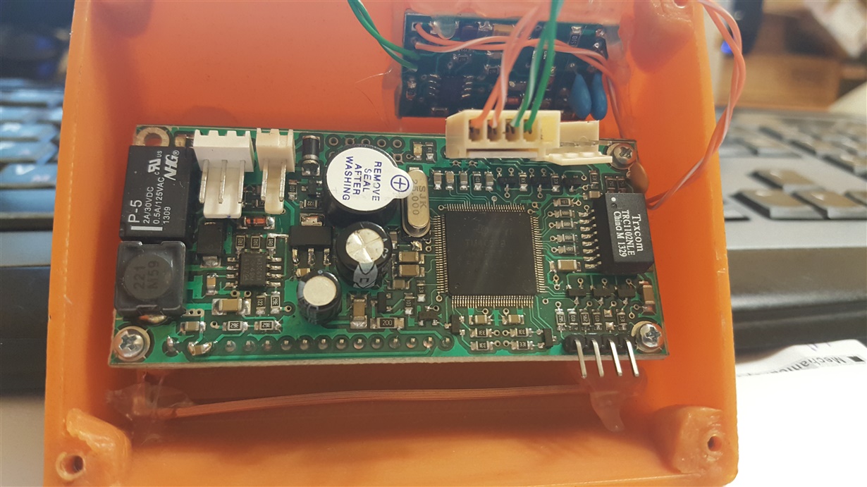
    The device has internal RFID reader 125 Khz. The wired magnetic antenna you can see at a foto. Tiva work inside magnetic field. It works all time because this a main function.


    P.S. Today we have 8 broken devices from 65.


    Alex Pas.
  • Hello Alex

    As you can see the current consumption for PCB#2 is way too high (even PCB#1 is not in the ball park). I would again request you to submit the failing devices to TI for analysis.
  • Hello Amit

    Send to TI a pcb or only IC? Send via Local distributor or directly? Can you tell me a mail addres.

    What I should do with devices are working now. Configure all unused gpio as Output or Input(+ WPU or WPD)...

    About my test:

    When a broken devices came from end customer. VDD line has about 1.2-4 Ohm to GND. After applying external power supply 3A@3.3V the current go to 2.8A for a short time and then go to lower value. I did such a test with 3 IC Tiva. And I have 5 broken disassemble Tiva IC and I did nothing with them after issue.

    Regards

    Pas Alex
  • Hello Alex

    Only the IC. You can send them via the Local Distributor. Do check with the distributor if they have a TI representative assigned to them, and it should be OK from then.

    Don't break the devices any further than they are already damaged. Otherwise the devices may be deemed damaged due to improper use. Also a description of the conditions when the failure is more likely to happen would be useful.