This thread has been locked.

If you have a related question, please click the "Ask a related question" button in the top right corner. The newly created question will be automatically linked to this question.

TMDSHVMTRINSPIN: Motor testing with TMS320F280049C and 3-phase power card

Part Number: TMDSHVMTRINSPIN
Other Parts Discussed in Thread: TMS320F280049C, , C2000WARE

Hi,team

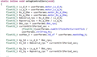
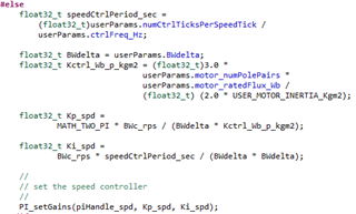
We are using TMS320F280049C controller, and Sensor less FOC code files given by TI,("C:\ti\c2000\C2000Ware_MotorControl_SDK_3_00_01_00\solutions\tmdshvmtrinspin\f28004x\ccs\sensorless_foc")

We designed own HV-kit with 3phase input supply, which generate 800Vdc bus, and we are using motor witch is having voltage 260V and current   7.4A ,is that FOC library support to my application ? 

1.we need to control the speed of my motor, how can i control ?

2.What are the parameters i need to change to control the speed (note : we familiar with motorVars.speedRefHz ) how can i control the output voltage of the inverter?

  • The FOC library is a software algorithm that is not related to the power supply voltage, and is dependent on the motor electrical parameters like Rs, Ls and Flux.

    You might take a look at the MotorControl SDK InstaSPIN Lab Guide and follow the steps in the guide to run the example labs using CCS, the guide can be found in 

    \ti\c2000\C2000Ware_MotorControl_SDK_<version>\solutions\common\sensorless_foc\docs\labs.

    You might try to run the lab01 to lab07 step by step if you are not familiar with the InstaSPIN-FOC examples in MotorControlSDK. Lab07 can be used for motor speed closed-loop control. You should use lab05 to identify the motor parameters (Rs, Ls and Flux) before running the lab07. And you must enure that the hardware kit is good for motor drive before running lab05 and lab07.

    The output voltage of the inverter will be set automatically by the FOC algorithm according to the running speed, adding load of the motor.

  • Hi Luo thanks for the reply,

    1. We are facing the problem in 4th lab ;

    problem: 1. My motor is ran successfully in the lab3, in lab4 it ran smoothly without any jerks or vibrations,but at the end if we set "  motorVars.flagRunIdentAndOnLine  to zero our motor giving one big sound and my fuse was blown. 

    Below are my user.h  settings as per my 3 phase HW 

    #define USER_ADC_FULL_SCALE_VOLTAGE_V         ((float32_t)(1200)
    #define USER_ADC_FULL_SCALE_CURRENT_A         ((float32_t)(20.0))
    #define USER_VOLTAGE_FILTER_POLE_Hz           ((float32_t)(1254.8))

    2. We set the USER_VOLTAGE_FILTER_POLE_Hz   based on the potential divider at DC voltage (as shown in below image),we refer spruhj1h for this calculations.


    3.We had seen one condition in that reference manual we shown that in below image 

    4.We got  USER_VOLTAGE_FILTER_POLE_Hz 1254.8 is this correct or do we need to change the capacitor value (47nF) to any other value ,
    5. we are not getting what is the need of this USER_VOLTAGE_FILTER_POLE_Hz  and where it can used in FAST, 

  • I have confusion with below parameters in user.h file ,how these values are set on what bases these values can calculated ?

    Can you please explain me this? because we are using own HW for this  

    #define IA_OFFSET_A (9.97279739) // ~=0.5*USER_ADC_FULL_SCALE_CURRENT_A
    #define IB_OFFSET_A (9.95302963) // ~=0.5*USER_ADC_FULL_SCALE_CURRENT_A
    #define IC_OFFSET_A (9.89870834) // ~=0.5*USER_ADC_FULL_SCALE_CURRENT_A


    //! \brief ADC voltage offsets for A, B, and C phases
    #define VA_OFFSET_V (0.990514159) // ~=1.0
    #define VB_OFFSET_V (0.986255884) // ~=1.0
    #define VC_OFFSET_V (0.983381569) // ~=1.0

  • You might use the lab02 to get these offset values, and then set these detection values in user.h. Generally, the three phase current and voltage sensing circuit may have a little bit difference.

    The default calculation values should be the same for each phase as below.

    IA/B/C_OFFSET_A = 0.5 * USER_ADC_FULL_SCALE_CURRENT_A

    VA/B/C_OFFSET_V= 1.0

    #define USER_VOLTAGE_FILTER_POLE_Hz           ((float32_t)(1254.8))

    You might increase the resistor or capacitor for voltage sensing circuit for getting a low USER_VOLTAGE_FILTER_POLE_Hz at 300~800Hz if your motor is not a low inductance and high frequency motor.

    Lab04 is just use the USER_ADC_FULL_SCALE_CURRENT_A for current closed-loop for hardware verification. You might check if PWM outputs turn on or turn off correctly without connecting the motor first in lab02 and lab03 first. And then check if the current and voltage sensing signals are correct in lab03 and lab04. If not, don't run the following labs with your own board.

  • Hi Luo thanks for the reply,

    1.We set IA/B/C_OFFSET_A ,from lab02 watch window, 

    2.We checked PWMs in lab02 and lab03,we observed that when we set motorVars.flagEnableSys to one then the PWMs are on with 50%duty cycle for 20Secs, after that the pulses are disappeared, next we set   motorVars.flagRunIdentAndOnLine  to one then pulses are on and we set motorVars.flagRunIdentAndOnLine to zero then pulses are turned off.

    3.We checked current waveforms in lab03, we got sine waves as shown in user guide.
    4.We are sensing voltages on phases as below, is that offset will effect the voltage values in code,

    5.In TI-HV-kit the voltages are given directly from the potential divider, without any offset value, that means the output at potential divider is -value to + value, but ADC range of TMS320F280049c is 0-3.3V only, how the FOC algorithm will consider this value? because we are giving this value to controller with 1.65 reference like current sensing circuit 

  • Hi Luo,
    Is this insaspin FOC  works for 7KW motors?

  • The software is not related to the power of the motor, but the high voltage kit can't be used for such high power motor.

    5.In TI-HV-kit the voltages are given directly from the potential divider, without any offset value, that means the output at potential divider is -value to + value, but ADC range of TMS320F280049c is 0-3.3V only, how the FOC algorithm will consider this value?

    Using 50% PWM duty on all of the three phase to sense the phase voltage values that should be equal to the half of the dc bus voltage. Use the sensed value to do the voltage sensing calibration that doesn't the offset for current sensing circuit. Actually, the voltage offset value is for voltage scale gain calibration between the three phases. Please follow the guide to set the offset values in the header file.

  • Hi, Luo thanks for the reply,


    1.We are using TI-hv kit, we programmed the  controller with lab03, we captured voltage wave forms at potential divider as shown in below image.

    2. we are getting voltage wave form with 1.24v offset( waveforms are shown in below), can you please explain me what is the reason for this offset value ?


    3.As per the HV-kit schematics, the voltages are directly connected to ADC pin without using any ISO Opamp,

  • The current and voltage offset are measured by using the 50% PWM duty on all of the three phase. The real current will be zero and the ADC input value should be about 1.65V equals to the offset reference voltage. The phase voltage will be equal to the half of the dc bus value, and the voltage offset value equals to the sensing phase voltage / dc bus voltage = 0.5 ( the latest version), or equals to 2.0 * sensing phase voltage / dc bus voltage = 1.0. The voltage offset value is a scale factor, not the measurement voltage. You might refer to the lab02 and the details about the lab in the guide.

  • Hi Luo, thanks for the response,

    We are trying to tune the ‘Kp’ and ‘Ki’ gains of Speed PI Controller and Current Controller. We need few clarifications from the below observations from the User Guide and actual Code.

    1. In labs.h we observed below formulas for Kp and Ki of speed controller (which I have copied here for reference).


         2. In the user.c, why the BWc_rps is multiplied with 100? And why Bwdelta value is 8? Can you please explain me on what basis these values are         selected?

            pUserParams->BWc_rps = MATH_TWO_PI * 100.0;

            pUserParams->BWdelta = (float32_t)8.0;

    3. Below is our Kp and Ki values from 7th Lab, from the above formulas

    4.We follow the user guide to tune the gains, but the formulas in the user guide are not matching with the labs.h formulas.

    Below is the user guide example image

    5.In the above example why the Bandwidth is taken 20 times lower than the sampling frequency? Why ꚍ = 1/200 in SpdKi calculation ?. Can you please explain me?

    6. And finally, these formulas are not matching with the formulas which are given in 7th Lab code. How can I calculate the Kp and Ki gains for our application based on the user guide?

    thanks 

  • This calculation values of the PI controllers are based on the motor parameters and the control bandwidth you want to achieve, which are just for your reference, you have to tune these parameters according to your system in a real case.

     2. In the user.c, why the BWc_rps is multiplied with 100? And why Bwdelta value is 8? Can you please explain me on what basis these values are         selected?

    As mentioned above. It's the setting control bandwidth and damping factor for reference, not the right value for every motor, you need to set the correct according to your motor. 

    You might take a look at some textbooks about the PID controller that could have more detailed description about these.

  • Hi Luo thanks for the reply,

    1. We are using our own 3-phase drive and InstaspinFOC (TMS320F280049C) provided by TI.
    2. In “is03_hardware_test “ lab our PMSM motor ran successfully, I have attached CCS wave forms in below(voltages,Currents,and SVGEN output).
    3. In “is04_signal_chain_test ” lab also my motor ran successfully.
    4. But in lab05 we are unable to identify the motor parameters correctly.and in Lab7 my motor not spinning
    5. Below are voltage, current scaling factors and PWM frequency 


                           #define USER_ADC_FULL_SCALE_VOLTAGE_V         ((float32_t)(1200.0))

                           #define USER_ADC_FULL_SCALE_CURRENT_A         ((float32_t)(20.0))

                          #define USER_VOLTAGE_FILTER_POLE_Hz               ((float32_t)(364.5))

                          #define USER_PWM_FREQ_kHz                                 ((float32_t)(5.0)) 

          6. Below are our motor parameters.     

    #if (USER_MOTOR == Estun_EMJ_04APB22_A)
    #define USER_MOTOR_TYPE MOTOR_TYPE_PM
    #define USER_MOTOR_NUM_POLE_PAIRS (3)
    #define USER_MOTOR_Rr_Ohm (2.4)
    #define USER_MOTOR_Rs_Ohm (4.86793718)
    #define USER_MOTOR_Ls_d_H (0.003608008015)
    #define USER_MOTOR_Ls_q_H (0.0036908008015)
    #define USER_MOTOR_RATED_FLUX_VpHz (3.1)
    #define USER_MOTOR_MAGNETIZING_CURRENT_A (NULL)
    #define USER_MOTOR_RES_EST_CURRENT_A (10.0)
    #define USER_MOTOR_IND_EST_CURRENT_A (0.0)
    #define USER_MOTOR_MAX_CURRENT_A (3.8)
    #define USER_MOTOR_FLUX_EXC_FREQ_Hz (10.0)
    #define USER_MOTOR_NUM_ENC_SLOTS (2500.0)
    #define USER_MOTOR_INERTIA_Kgm2 (3.10002e-05)

    #define USER_MOTOR_FREQ_MIN_HZ (5.0) // Hz
    #define USER_MOTOR_FREQ_MAX_HZ (60.0) // Hz

    #define USER_MOTOR_FREQ_LOW_HZ (5.0) // Hz
    #define USER_MOTOR_FREQ_HIGH_HZ (50.0) // Hz
    #define USER_MOTOR_VOLT_MIN_V (45.0) // Volt
    #define USER_MOTOR_VOLT_MAX_V (300.0) // Volt

         7.  Below are our voltage, current sensing current and DC_bus voltage sensing.

    8..Below are voltage and current wave forms in 3rd lab

    9. SVGEN outputs

    thanks in advance

  • Please make sure that the below parameters are calculated correctly according to your own board. And don't add a big filter capacitor on current sensing circuit, ensure the cut-off frequency of the filter for current signals must be far higher than PWM frequency.     

           #define USER_ADC_FULL_SCALE_VOLTAGE_V         ((float32_t)(1200.0))

           #define USER_ADC_FULL_SCALE_CURRENT_A         ((float32_t)(20.0))

           #define USER_VOLTAGE_FILTER_POLE_Hz               ((float32_t)(364.5))

    And what's the delay time of the isolation amplifier for current and voltage sensing? If the delay time are different, and the one for current is higher, that could be an issue for using InstaSPIN-FOC.