This thread has been locked.
If you have a related question, please click the "Ask a related question" button in the top right corner. The newly created question will be automatically linked to this question.
Hi all:
I would like to implement Phase Shifted Full Bridge topology with PCMC with the help of 280025C micro-controller.
I referr to the Design guide : TIDM_02000.
I want to use Mode2 for SR Mode for efficiency.
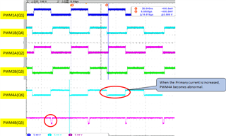
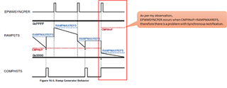
If the Primary current is greater than the Ramp MAX value, there is an error in the SR PWM waveform.
I found the similar issue on the forum, It seems to be unresolved.
The link is as below.
TMS320F280025C: phase shift PCMC , some question obout SR PWM - C2000 microcontrollers forum - C2000︎ microcontrollers - TI E2E support forums
If this problem has been resolved, I would like to be assisted in this issue.
Thanks in advance.
The error waveform is as shown below.
Normal (Primary current <Ramp MAX value)
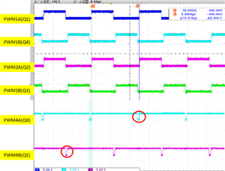
Abnormal (Primary current> Ramp MAX value)
Hi,
If the Primary current is greater than the Ramp MAX value
What do you mean by Ramp Max. Are you referring to the DAC initial value which is also the initial value of the ramp?
If yes, how can primary current be greater than ramp max since we need the slope compensation?
Trying to understand your question.
Regards,
Chen
Hi Chen,
Ramp is the initial value of DAC, which means RAMPMAXREFS in terms of registers.
As an evaluation environment, a voltage is applied to the DAC terminal (CMPx_HP) with a regulated power supply. Software is open loop control software.
In the above case, the CMPINxP> RAMPMAXREFS situation easily occurs.
Even with closed-loop software, if the condition of CMPINxP> RAMPMAXREFS is satisfied, same error occurs.
For example, due to sudden changes in load, noise etc.
Yukihiko,
Apologies for the delay on our side. Chen is out of the office, but should be back and reply tomorrow the 29th US time.
Best,
Matthew
Thank you for your reply.
I adjusted the dead band and checked it.
It has not been solved.
I doubt the following:
・ Link mistake with PWM2
・ Built-in comparator setting
I want an early answer.
Hi Yukihiko,
Are you using the same configuration of figure 3-4 of the user guide? I am surprised only SR PWM will be abnormal since SR logic is based on primary side PWM. Looks like it is more like a configuration issue. Could you double confirm the signal chain and the TIDM-02000 code (it has SR mode 0, 1 and 2)
Regards,
Chen