This thread has been locked.

If you have a related question, please click the "Ask a related question" button in the top right corner. The newly created question will be automatically linked to this question.

TMS320F28379D: Routing QA and QB from CLB to EQEP

Part Number: TMS320F28379D
Other Parts Discussed in Thread: SYSCONFIG

Hello,

I have a problem with passing/injecting signals from CLB1 to EQEP1. I used XBAR and CLB XBAR to route QEPA and QEPB signals to CLB and then just pass them from input to output.

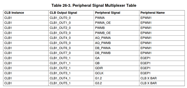
Problem is, that if I connect the signals to OUTLUT_0 and OUTLUT_1 and then enable outputs 8 and 9, the EQEP1 shows nonsense values. If I pass them from CLB to PWMA/B they look as they should.

I tried to route the QEPA/B signals to other outputs, but with no luck. The question is: where are QA and QB or are they even connected to EQEP1 module ?

  • Tomas,

    When you say pass them to EQEP1 by enabling output 8/9, what exactly doe you mean by that?

    This table does not show any connection to EQEP from the CLB.

    Nima

  • Hello,

    the table you showed is for CLB inputs, but I want to deal with CLB outputs, see table below.

    I need to pass signal from inside CLB to QA/QB signals of EQEP1, but if I do so according to the table above, it does not work. It seems that OUT0_1 and OUT1_1 act as QDIR and QCLK. I also tried to use OUT2_1 and OUT3_1 as QA and QB, but it does not work either. Then I tried the same with CLB2 and EQEP2 and CLB3 and EQEP3, however still no luck.

  • I just ran some tests and looked at the HW and you may be correct about QA/QB and QDIR and QCLK being reversed.

    Let me check with design and get back to you.

  • Hi Tomas,

    This is an error in our documentation, we will correct this as soon as possible.

    The correct outputs should be:

    CLBx_OUT0_1 -> QCLK

    CLBx_OUT1_1 -> QDIR

    CLBx_OUT2_1 -> QB

    CLBx_OUT3_1 -> QA

    Thank you,

    Luke

  • Hi Luke,

    I did test QB and QA, and it does not work. My CLB design is shown below, where in0 is QA, in1 is QB, in2 and in3 are used to invert QA or/and QB through bits of CLB GP register. The state machine and the LUT2 is used to convert QA and QB to QDIR and QCLK signals, this approach which works well.

    I connected QA and QB to other CLB outputs (not just 2 and 3) to test the rest of possible combinations, but it does not work either.

    Is it possible that QA and QB signals of eQEP are not connected to CLB at all ?

  • Hi Tomas, I have confirmed the connections I described in my previous post. Is the state machine and LUT's sole purpose to convert QA and QB to QCLK and QDIR due to this TRM error? If so, you should just be able to route your signal to a different output to resolve this issue.

    Also just clarify, you have tried replacing QA and QB to QCLK and QDIR, respectively. This still did not work?

    If so, could you share your .sysconfig file so I could test your configuration?

    Thank you,

    Luke

  • Hi Luke,

    yes, I implemented QEP decoder (QA+B to QDIR+CLK0) with LUT and FSM. This approach works when I assign QCLK to CLBx_OUT0_1 and
    QDIR -> CLBx_OUT1_1. The Clb1LogicCtrlRegs.CLB_OUT_EN register is set to 0x300.

    But if I switch to my "raw" input signals QA and QB which are assigned to CLBx_OUT2_1 and CLBx_OUT3_1 by setting CLB_OUT_EN to 0xC00 then the eQEP1 does not work. I have the register Eqep1Regs.QDECCTL set to 0 which is correct (QSRC=0b00) for this mode.

    My .syscfg file can be found here.

    Tomas

  • Hi Tomas,

    Thanks for your file. I did some testing and I am seeing similar behavior where QA and QB are not accessible from the CLB. In my testing, I am using ePWM to generate quadrature signals to the eQEP peripheral, and using the CLB to connect the signals. 

    If I route the ePWM signals to the eQEP peripheral signal externally without the CLB, my eQEP functions as what I would expect. However, once I configure the CLB to route the signals and override QA and QB, the eQEP is not functioning. Also even when the QA and QB signals are overridden by the CLB, I can still route the signals externally from the ePWM to the eQEP and have the eQEP peripheral function, but this shouldn't be the case if QA and QB are overridden.

    I will have design run some tests to validate this and see what CLBx_OUT2_1 and CLBx_OUT3_1 really are, as I suspect they are not QA and QB.

    Regards,

    Peter

  • Hi Tomas,

    I have sent some examples for the design team to test, I've confirmed Peter's suspicion that the output override function does not seem to function as implied by the TRM for QA and QB, although there are no issues for QCLK and QDIR. I will get back to you as soon as we have more information from the design team.

    --Luke

  • Hi Tomas,

    We are still waiting to hear back from the design team on test results for this. I'll let you know as soon as we have more information on this issue.

    --Luke

  • Hi Tomas, we are still confirming this table with the design team. I will provide you an update once we have more information.

    --Luke

  • Hi Tomas, we are still confirming this table with the design team. I will provide you an update once we have more information.

    --Luke

  • Hi Tomas, we are still confirming this table with the design team. I will provide you an update once we have more information.

    --Luke

  • Hi Tomas,

    We verified these connections with design. The QA and QB referenced in this table are internal signals and not intended to be used by the customer. They are not overriding the QA and QB inputs to the decoder. We will remove these signals from this table in our documentation to reduce confusion for customers.

    Thank you,

    Luke