This thread has been locked.

If you have a related question, please click the "Ask a related question" button in the top right corner. The newly created question will be automatically linked to this question.

TMS320F280041C: TMS320F280041C: Autobaud fails after kernel load

Part Number: TMS320F280041C
Other Parts Discussed in Thread: LAUNCHXL-F280049C, MOTORWARE, C2000WARE

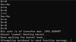
I'm trying to get the serial flash programmer to work on custom firmware with a F280041C. The kernel successfully loads on the device before flashing custom firmware. The program stops at the attempting autobaud message.

The command I am using is this:

serial_flash_programmer.exe -d f28004x -k C:\ti\c2000\C2000Ware_5_01_00_00\utilities\flash_programmers\serial_flash_programmer\f28004x_fw_upgrade_example\flashapi_ex2_sci_kernel.txt -a C:\ti\c2000\C2000Ware_5_01_00_00\utilities\flash_programmers\serial_flash_programmer\f28004x_fw_upgrade_example\led_ex1_blinky.txt -p COM5 -v

I tried getting the LAUNCHXL-F280049C to replicate the issue, but the device successfully locks with the autobaud and the DFU process works fine. I can also flash my custom firmware .txt file.

I recompiled the flashapi_ex2_sci_kernel project in CCS studio and it works on the LAUNCHX-F280049C (CPU1_RAM is the only build target that would work on the LAUNCHXL-F280049C), but still crashes at autobaud on my hardware.

I have checked that the device is booting into SCI and that the SCI Pins are defaults 28 and 29. I don't think the kernel would be able to load to the device if it wasn't in the SCI bootmode, is this correct?

Could the problem be caused by the difference in flash size between the 2 devices? F280049C is 256KB while F280041C is 128KB.

Could this require a change to the 28004x_generic_ram_lnk.cmd in the Kernel project?

The custom hardware for the SCI port and SCI bootmode settings are nearly identical to the LAUNCHXL-F280049C, so I don't think it is a hardware problem but I haven't ruled that out completely.

Thanks,

James

  • Hi James,

    Correct, the kernel would not load to the device if it was not in SCI boot mode (w/ required GPIO pins). 

    Even for the difference in flash size, if it is getting stuck at autobaud that means the issue arises before downloading the application image. There is a part of the errata for this device that mentions during SCI the SCIHBAUD needs to be cleared before calling the SCI ROM bootloader (TMS320F28004x Real-Time MCUs Silicon Errata (Rev. G)). This is something I can look into.

    The linker cmd file for the kernel project should be edited to reflect the flash range for the F280041C device.

    Thanks and regards,

    Charles

  • Thanks for pointing out the errata for SCI boot. I think this is the most likely cause of my issue. It's strange that even with the SCI bootloader errata the process works flawlessly on the LAUNCHXL-F280049C.

    Regarding the flash sectors, my application is only occupying 25% of FLASH_BANK0 on the F280041C. I have removed any instances of BANK1 from the 28004x_generic_ram_lnk.cmd file even though I don't think that was causing a problem(yet).

    I'm not sure if I fully understand how to clear the SCIHBAUD before calling the SCI ROM bootloader. When performing a device reset with the boot pins held in the SCI state, does the SCI ROM bootloader execute right away?

    After the serial flash programmer downloads the kernel to the device it waits for the kernel to boot before attempting autobaud again. Are we thinking that the bootloader never branches to the kernel? The kernel seems to have code for resetting the SCIHBAUD to zero before attempting autobaud lock.

    static inline void
    SCI_lockAutobaud(uint32_t base)
    {
        //
        // Check the arguments.
        //
        ASSERT(SCI_isBaseValid(base));
    
        //
        // Prime the baud register
        //
        HWREGH(base + SCI_O_HBAUD) = 0x0U;
        HWREGH(base + SCI_O_LBAUD) = 0x1U;
    
        //
        // Prepare for autobaud detection.
        // Set the CDC bit to enable autobaud detection and clear the ABD bit.
        //
        HWREGH(base + SCI_O_FFCT) |= SCI_FFCT_CDC;
        HWREGH(base + SCI_O_FFCT) |= SCI_FFCT_ABDCLR;
    
        //
        // Wait until we correctly read an 'A' or 'a' and lock
        //
        while((HWREGH(base + SCI_O_FFCT) & SCI_FFCT_ABD) != SCI_FFCT_ABD)
        {
        }
    
        //
        // After autobaud lock, clear the ABD and CDC bits
        //
        HWREGH(base + SCI_O_FFCT) |= SCI_FFCT_ABDCLR;
        HWREGH(base + SCI_O_FFCT) &= ~SCI_FFCT_CDC;
    }

  • Hi Charles,

    I managed to figure out the solution to this problem. The clock frequency in the SCI Kernel was not set correctly for my device.

    In flashapi_ex2_sci_kernel.c when it includes "device.h" it uses the 20 MHz XTAL as the clock source whereas my hardware with the F280041C uses the 10 MHz internal oscillator. I had to debug the kernel application on my hardware using the XDS110 debug probe and step through the code to figure this out.

    This may not have been a problem if I was using the same "device.h" from my main application where I already adjusted the clock frequency settings, it's because I have a separate MotorWare project directory from the C2000Ware directory where I found the kernel source.

    It also seems that the SCIHBAUD register errata was not an issue for either board.

    Thanks for your help, hopefully this information can be helpful for others.

    Here is the code for the clock frequency in "device.h" for the flashapi_ex2_sci_kernel project:

    //*****************************************************************************
    //
    // Defines related to clock configuration
    //
    //*****************************************************************************
    //
    // 20MHz XTAL on controlCARD and Launchpad. For use with SysCtl_getClock().
    //
    //#define DEVICE_OSCSRC_FREQ          20000000U
    
    // Internal OSC2 10MHz freq
    //
    #define DEVICE_OSCSRC_FREQ          10000000U
    
    //
    // Define to pass to SysCtl_setClock(). Will configure the clock as follows:
    // PLLSYSCLK = 20MHz (XTAL_OSC) * 10 (IMULT) * 1 (FMULT) / 2 (PLLCLK_BY_2)
    //
    //#define DEVICE_SETCLOCK_CFG         (SYSCTL_OSCSRC_XTAL | SYSCTL_IMULT(10) |  \
    //                                     SYSCTL_FMULT_NONE | SYSCTL_SYSDIV(2) |   \
    //                                     SYSCTL_PLL_ENABLE)
    
    // Use the internal OSC2 times 10 to achieve a 100MHz clock
    #define DEVICE_SETCLOCK_CFG         (SYSCTL_OSCSRC_OSC2 | SYSCTL_IMULT(20) |  \
                                         SYSCTL_FMULT_NONE | SYSCTL_SYSDIV(2) |   \
                                         SYSCTL_PLL_ENABLE)
    
    //
    // 100MHz SYSCLK frequency based on the above DEVICE_SETCLOCK_CFG. Update the
    // code below if a different clock configuration is used!
    //
    //#define DEVICE_SYSCLK_FREQ          ((DEVICE_OSCSRC_FREQ * 10 * 1) / 2)
    #define DEVICE_SYSCLK_FREQ          ((DEVICE_OSCSRC_FREQ * 20 * 1) / 2)
    
    //
    // 25MHz LSPCLK frequency based on the above DEVICE_SYSCLK_FREQ and a default
    // low speed peripheral clock divider of 4. Update the code below if a
    // different LSPCLK divider is used!
    //
    #define DEVICE_LSPCLK_FREQ          (DEVICE_SYSCLK_FREQ / 4)