This thread has been locked.
If you have a related question, please click the "Ask a related question" button in the top right corner. The newly created question will be automatically linked to this question.
Hi,
Initially, we tried with Lauchpad157 & Drv8353 board interface working fine without issue.
Now, Working on a custom board with TMS320F2800157 MCU.
The same software(Lauchpad157 & Drv8353 board) when adapted to a custom board faces an issue while trying with the DMC_LEVEL_1 build.
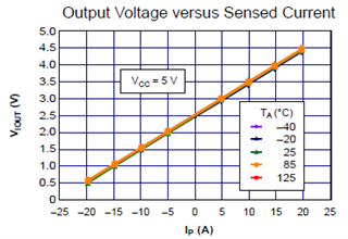
Getting faults like Current offset (Hall effect sensor used how to calibrate)
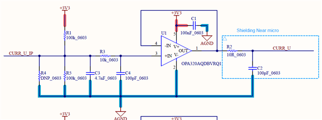
The custom board contains TMS320F280157 MCU and a Separate Power board(FET Drivers) . Used DRV8353 macros but removed DRV8353-related Stuff.
Current offsets reading in expression windows are not as per the UMC document. because we are using a Hall effect sensor, not a shunt resistor?
how to calibrate the current offset for the Hall effect sensor?
Any help is much appreciated. Thanks in Advance.
Hi,
You should use this sensor such that it provides current sense output within the C2000's ADC range (Max 3.3V, depends on VREF used). I see it takes 5V power, so you should use care and check its output range based on current being measured. Also verify offset usage is correct for in-line phase sensing (ideally half full-scale ADC range).
Best,
Kevin
Hi Kevin Allen18,
Yes, the Sensor used is 5V operating.
Could you please elaborate on how to change or adapt 5v for 3.3v and what values have to be given to ADC half full-scale range?
Hi Kevin Allen18,
Can we have a short call to check this in custom hardware?
Please let me know your availability.
Hi,
Could you please elaborate on how to change or adapt 5v for 3.3v and what values have to be given to ADC half full-scale range?
Check your ACS712 device datasheet. It has info on the output voltage vs. sensed current. It also depends on the Current Sensing Range, IP (A), of your device, see below as an example from the Datasheet. The output voltage can exceed the C2000 ADC voltage range and damage the device in this case (IP = 20 A).
Do you have an Op-Amp or any circuitry to scale the output of the ACS712 device before the signal enters the C2000 ADC?
Best,
Kevin
yes we are using op-amp circuit to convert 5v to 3v while connect to c2000 device
Hi,
I'm not sure how the circuit you shared scales the 0-5v output to be within ADC 0-3.3v range (depending on your ADC voltage reference).
You can check what the voltage on the ADC pin is when there is zero current being sensed to understand what the offset should be. You probably also need to calculate your current scaling factor for the software based on your sensing circuitry.
Best,
Kevin