This thread has been locked.

If you have a related question, please click the "Ask a related question" button in the top right corner. The newly created question will be automatically linked to this question.

LAUNCHXL-F280049C: Double pulse generation using the EPWM module

Part Number: LAUNCHXL-F280049C
Other Parts Discussed in Thread: C2000WARE, SYSCONFIG

Hi,

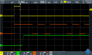
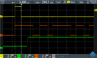
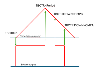
I am trying to generate a single double-pulse signal for driving a MOSFET double pulse testing rig using the EPWM module. The goal is to achieve a waveform similar to what is shown in the following figure: 

I believe this should be fairly easy to implement on the launchpad. However, as I am totally new to the development platform, I have been struggling with this for a while now. 

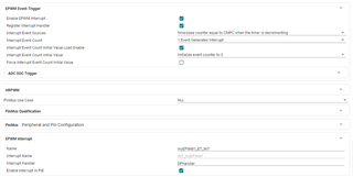
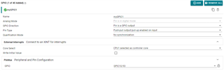
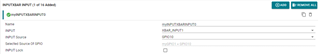
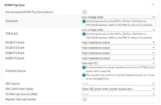
The approach that I have taken relies on the EPWM Trip Zone and event trigger submodules. I am able to generate the desired waveform using the CMPA and CMPB counter compares using the SYSCFG file, as shown in the picture. I am using the Event-Trigger submodule to generate an interrupt after every cycle. I have GPIO1 configured as an INPUTXBAR source in the SYSCFG file (gpio configured as input : push-pull output/ pull-up enabled on input). The idea is that when the interrupt is generated, it is handled in the interrupt void where GPIO0 is toggled, tripping the one-shot TZ1 (through the XBAR) and forcing the EPWM output to a low state. 

Here is what I have got done with the help of various c2000ware examples and the C2000 ePWM developer's guide as well as similar problems found on this forum:

Fullscreen
1
2
3
4
5
6
7
8
9
10
11
12
13
14
15
16
17
18
19
20
21
#include "driverlib.h"
#include "device.h"
#include "board.h"
uint32_t epwm1IntCount;
__interrupt void DPhandler(void);
void main(void)
{
epwm1IntCount = 0U;
Device_init(); // Initialize device clock and peripherals
Device_initGPIO(); // Disable pin locks and enable internal pull-ups.
Interrupt_initModule(); // Initialize PIE and clear PIE registers. Disables CPU interrupts.
Interrupt_initVectorTable(); // Initialize the PIE vector table with pointers to the shell Interrupt service Routines (ISR).
Board_init();
SysCtl_disablePeripheral(SYSCTL_PERIPH_CLK_TBCLKSYNC); // Disable sync(Freeze clock to PWM as well)
EPWM_setSyncOutPulseMode(myEPWM1_BASE, EPWM_SYNC_OUT_PULSE_ON_COUNTER_ZERO); // ePWM1 SYNCO is generated on CTR=0
Interrupt_enable(INT_EPWM1);
XXXXXXXXXXXXXXXXXXXXXXXXXXXXXXXXXXXXXXXXXXXXXXXXXX

With the current solution, a single 4.6us pulse is generated, even though I have the timer period as well as the CMPA and CMPB values configured so that pulse1 should be 10us and pulse2 4us, with 3us between them. Below are the .syscfg configurations of the EPWM module. The TBCTR is configured to count down from the initial counter value 100 after sync event to make sure that the action qualifier event "time base counter equals zero" is catched. 

Is my approach even applicable? I would highly appreciate any help with this. 

As explained, right now I have configured the EPWM, GPIO, and INPUTXBAR using the .syscfg file. How does the SYSCFG come in play, if I want to configure the epwm duty cycles in the .c code? Will the configurations made in the .syscfg be overwritten? This might be something that I will want to do in the future, if I want to control the pulse widths using parameters. 

Thank you very much for your help.

Best regards,

Juhani

  • Hi Juhani,

    Thanks for the detailed post, and glad you have been able to use some of the existing resources so far!

    Your approach seems correct to me, but would you be able to provide some oscilloscope shots of the behavior you are seeing? (would like to see your PWM signal as well as the GPIO signal used as the trip source to see the timing of the trip, and thus the timing of the ISR occurring). Do you get any different behavior if you start the counter from 0, counting up?

    In regard to SysConfig and .c code usage:

    • board_init() is the function to call SysConfig-generated code; so depending on where this is in your application code, it will overwrite configurations that you have written prior to board_init().
    • ^That being said, you can use driverlib/bitfield/SysConfig together with no logistical issues. Just have to be careful about the order of your code/what functions you use so you don't overwrite what was configured before (meaning you can alter your configurations after board_init() is called and it won't be overwritten by SysConfig)
      • If you didn't already know, you can view SysConfig-generated code by clicking on the <> arrows in the upper-right hand corner and clicking on the 'board.c' file - this will show code changes live as you update SysConfig settings.

    Best Regards,

    Allison

  • Hello Allison,

    Thank you for the quick response.

    While further studying the system's behavior with an oscilloscope, I noticed that TZ1 will always trip, even if the gpio is not toggled at any point. In fact, toggling the gpio does not seem to do anything. I also noticed that disabling the event-trigger epwm interrupt does not affect the the output at all either. The behavior does not differ when starting the counter from 0, counting up. 

    Here's what the output looks like when epwm interrupt is disabled and the gpio is not toggled at any point. I have also commented out the interrupt configuration commands from the code:

    C1 (yellow line) is the EPWMA output which is being pulled low, C2 (green) is the GPIO output used to trip TZ1 and C3 (red) is the EPWMB output. EPWMB is configured in the action qualifier exactly as EPWMA, but in the Trip Zone submodule the TZB event is disabled so the the output isn't tripped by the one shot trip. The pwm signal looks good (high 10us, low 3us, high 4us repeating). 

    It seems that something is tripping the TZ1, pulling the EPWMA low. The XBAR input source GPIO pin is also somehow toggled. These don't happen simultaneously, both events occur on seemingly random times. 

    Here's what the output looks like with the EPWM interrupt enabled:

    Enabling the epwm interrupt seems to only affect some of the timings. The EPWMA output is the same. 

    Do you have any idea what could be causing the TZ1 trip?

    Best regards,

    Juhani

  • Hi Juhani,

    This makes me think there could be some configuration issue perhaps with the GPIOs. Could you double check which GPIOs you are using for each signal? (e.g. GPIO0 for EPWM1A, GPIO1 for EPWM1B, etc.) as well as what pins you are scoping and what pins you are setting in the PinMux panels of the peripherals on SysConfig? Perhaps it'd be helpful for you to share your SysConfig file with me.

    Some other things to try:

    • Check to see if you see the interrupt count increase when you run the program.
    • Have you tried using the "step into" and "step over" buttons to walk through each line of code? Sometimes this can be helpful while viewing the register settings in the CCS window to watch them change live while you step through lines of code and make sure things are being configured how you want.
    • Have you referenced the EPWM trip zone C2000Ware examples? And if so, which one?

    Best Regards,

    Allison

  • Hello Allison,

    Thank you very much for your help. Your recommendations gave me plenty to consider. 

    First of all, I had been clearing the wrong interrupt group. On my device EPWM1 is assigned to group 3. I also needed to configure the EPWM interrupt handler by enabling the register interrupt handler in the event-trigger submodule and enabling the interrupt in PIE.

    The problem of something tripping the TZ1 seemed to happen when the GPIO configurations are loaded by Board_init(). For some reason that cannot be seen in the screenshots in my last reply, but the GPIO output always jumps high for a moment when starting the program. This causes the one-shot interrupt which is needed to be acknowledged in order to continue.

    As I had noticed, the interrupts seemed to affect some of the timings of the output signal. To achieve the 10us and 4us pulses consistently, I changed it so that the interrupt event occurs when the TBCTR=CMPC when the timer is decrementing, and set CMPC so that the compare event is triggered right after the second pulse is set low. For some reason I couldn't use CMPA for this, maybe it cannot be used for two compare events simultaneously. 

    I'm posting the working code and the event trigger interrupt configurations here as well, in case someone will find them helpful:

    Fullscreen
    1
    2
    3
    4
    5
    6
    7
    8
    9
    10
    11
    12
    13
    14
    15
    16
    17
    18
    19
    20
    21
    #include "driverlib.h"
    #include "device.h"
    #include "board.h"
    uint32_t CTR0Count;
    __interrupt void DPhandler(void);
    void main(void)
    {
    CTR0Count = 0U;
    Device_init(); // Initialize device clock and peripherals
    Device_initGPIO(); // Disable pin locks and enable internal pull-ups.
    Interrupt_initModule(); // Initialize PIE and clear PIE registers. Disables CPU interrupts.
    Interrupt_initVectorTable(); // Initialize the PIE vector table with pointers to the shell Interrupt service Routines (ISR).
    SysCtl_disablePeripheral(SYSCTL_PERIPH_CLK_TBCLKSYNC); // Disable sync(Freeze clock to PWM as well)
    Board_init();
    // Board_init() causes a TZ1 trip, causing a one-shot interrupt which is needed to be acknowledged in order to continue
    XXXXXXXXXXXXXXXXXXXXXXXXXXXXXXXXXXXXXXXXXXXXXXXXXX


    Best regards,

    Juhani