Part Number: TMS320F28388D
Other Parts Discussed in Thread: UNIFLASH,
Tool/software:
Dear Team
We are using the C2000 Hex Utility for generating hex files. However, We have observed a discrepancy in the output when using different commands for hex file generation, which is causing compatibility issues with third-party tools and flashing software.
The two command options are:
-
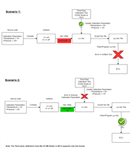
Hex Generation Command Option 1 : -order MS -romwidth 16 -q --memwidth=16 -> Option which work for uniflash but for not VcdmStudio
-
Hex Generation Command Option 2 : -order MS -romwidth 16 -q --memwidth=8 -> Option which work for vcdmstudio but for not uniflash
When we use the first command, the hex file is generated successfully but the parameters required for calibration are not visible in third-party tools such as INCA and VCDM Studio. As a result, we are unable to update the parameter values in the hex file (Offline Calibration).
On the other hand, when we use Command 2, the hex file is generated successfully and the parameters used for calibration are displayed correctly in the third-party tools. We are able to update the parameter values in the hex file without any issues. However, we are unable to flash the file in the microcontroller using Uniflash tool, which throws an error.

Could you please help us understand the difference between these two commands and why Command 1 is not generating a hex file compatible with offline calibration? Additionally, why is Command 2 not generating a hex file compatible with Uniflash flashing software?
Attached are the Command 1 and Command 2 artifacts: Hex file, map file, out file, linker file, a2l file.