This thread has been locked.

If you have a related question, please click the "Ask a related question" button in the top right corner. The newly created question will be automatically linked to this question.

TMS320F28035: SCI RX interrupt without FIFO not working

Part Number: TMS320F28035
Other Parts Discussed in Thread: C2000WARE

Hello Guys,

I am using F28035 Control card with Docking station USB EMU [R3] for my project.

I am facing problems with the control card, and I was unable to find any workable solution on the discussion forum.

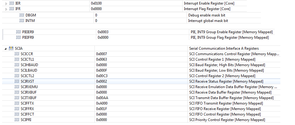
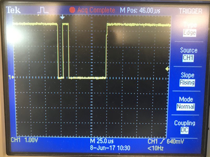
1 – I am unable to generate a SCI RX interrupt (not using FIFO), I have verified all the register settings, still I am not getting Rx interrupt over SCI. But TX interrupt is working fine. In my setup I am communicating directly between the PC and MCU control card. Do you have any comments on this?

Here is what I have already tried - 

A - I removed R27 on the control card and directly connected the UART cable to the GPIO 28 & 29

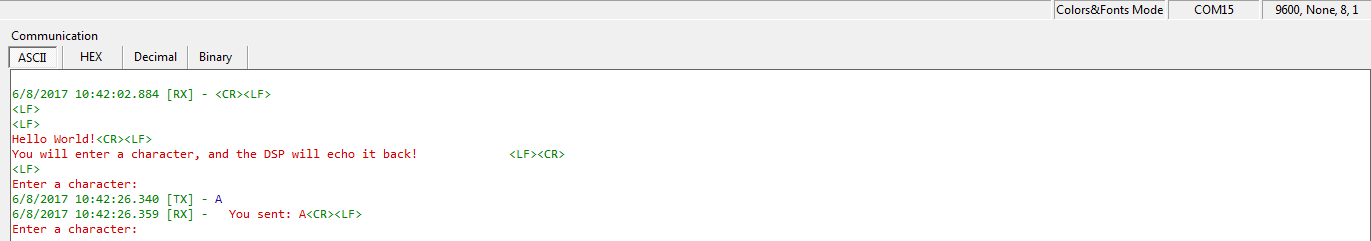
B - Example "Example_2803xSci_Echoback" from the Control suite works fine, but that doesn't use the Interrupt.

B - When I enable loopback mode in my code, I can see RX interrupt working but I don't see the RX interrupt when I disable the Loopback mode

C - I tried various other options discussed in the other posts like disable the FIFO interrupt, Disable FIFO but no luck.

Please let me know if, I am missing any important thing.

Regards

Amjad

  • Have you enabled the interrupt in the SCI and also in the PIE and also in the IER register?

    Please see the SCI interrupt example for F2837x in C2000Ware.

    sal
  • Hello Sal,

    Thanks for the response.

    The example SCI interrupt is using FIFO, but I need SCI using interrupt without FIFO. For your information - all the 3 examples are working fine.

    Yes, I have enabled the SCI interrupts.

    Here, are the init codes:-

    The SCI setting are:-

         GPIO_setMode(28,GPIO_28_Mode_SCIRXDA);

          GPIO_setMode(29,GPIO_29_Mode_SCITXDA);

          CLK_enableSciaClock();

          /*Setup SCI Peripheral*/

          SCI_disable();

          SCI_setNumStopBits(SCI_NumStopBits_One);

          SCI_disableParity();

          SCI_setCharLength(SCI_CharLength_8_Bits);

          SCI_enableRxErrorInt();

          SCI_enableTx();

          SCI_enableRx();

          SCI_setBaudRate(SCI_BaudRate_115_2_kBaud);//update the enum as per the LPSCLK, here LPOSCLK = 15e+6

          SCI_enableRxInt();

          SCI_enableTxInt();

          //SCI_enableLoopBack();

          SCI_disableRxFifoInt();

          SCI_disableTxFifoInt();

          SCI_disableFifoEnh();

          SciaRegs.SCIFFRX.bit.RXFIFORESET = 0;

          SCI_enable();

    /*Interrupt Enable */

          IER |= M_INT9;

          PieCtrlRegs.PIEIER9.bit.INTx1  = 1;

          PieCtrlRegs.PIEIER9.bit.INTx2  = 1;

          EINT;   // Enable Global interrupt INTM

          ERTM;   // Enable Global realtime interrupt DBGM

    Register values from the debug:-

    Please let me know, if I am missing anything.

    Regards

    Amjad

  • Can use see if the RXBUF is receiving any data or if there is any data on the RX pin please?

    You need to make sure data is actually getting to the SCI first.

    sal
  • Hello Sal,

    I can see data on the RX line using Scope.
    And I CANNOT see data in RXBUF.

    Also, with same hardware, I am able to run the "Example_2803xSci_Echoback" fine. It works fine for both Transmit and Receive. - Only difference is the Interrupt Source, this example is not using SCI SCIRXINTA_ISR.

    Regards
    Amjad
  • Amjad,

    when you are trying to receive data from the PC what is the status of the receiver's error flags? These can be found in the SCIRXST register(RXERROR, BRKDT, FE, OE, PE) a description of each of these can be found in table 13 of the SCI Reference Guide.

    My guess is that your code is setting up the SCI to a different baud rate/parity/etc. than the Echoback example. This would likely cause the RXERROR flag to be set, which shuts down the SCI receiver until your application code resets the reciever.

    Regards,
    Cody

  • Hello Cody,

    Thanks for your response.

    There is no change in the SCIRXT Register, all the values are zero except the RXWAKE bit, which makes sense.

    I don't think so, there is any baudrate/parity related issue. You can refer to the screenshots of the register values in debug. And, I have written the code such a way that after startup MCU transmits few bytes, which I am receiving perfectly fine.

    Regards
    Amjad
  • Amjad,

    I agree that if no flags are set then your baurate/ parity are likely not currently the issue.

    Please confirm my understanding:

    Using your code with internal loopback disabled: you do not see anything in the RX register.

    Using the exact same code with internal loopback enabled: everything works as expected.

    Regards,
    Cody

  • Hello Cody,

    Thanks for your response.

    Yes, your understanding is correct.

    When I enable the internal loop-back mode, I can see both interrupts (Rx & Tx).

    But when I disable the internal loop-back mode, I can see only TX interrupt and NO Rx Interrupt.

    Regards

    Amjad

  • Can you confirm that data is on the RX line with an oscilliscope please?

    sal
  • Hello Sal,

    Yes Sure.

    1. I have captured two images for my existing SCI Rx/Tx code:-

    • Scope capture - capture the moment when I am sending data 0x01 from the PC on SCI Rx line.

    • Terminal Screen capture - You see first The MCU sends 0xAA to PC, then PC tries to send 0x01 to the MCU - But the MCu didn't get the that, and no RX interrupt

    I have also captured the data on the terminal screen for the example "Example_2803xSci_Echoback" for F28035


    Please note - The hardware connection are exactly same for both tests.

    If you want, I can share you the my source code to your Official TI email id.(Not on the forum here)

    Regards

    Amjad

  • Amjad,

    we're obviously overlooking something simple here...

    1. What is the value of SCICTL1.RXENA?
    2. What is the value of SCICTL1.SLEEP?
    3. Are you using Auto-Baud?
    4. Are you using multiprocessor mode(I don't expect you to, as this is a simple point to point communication)?

    Could you run the device with SCIRX connected to the PC

    1. observe that its failing
    2. pause the device execution
    3. disconnect the PC
    4. enable internal loopback by setting the LOOPBACK ENA bit using the memory browser(do not reset the device)
    5. Resume running from where you paused it and observe the status(are any error flags set, is the receiver working correctly, etc.)

    Hopefully this brings us closer to a resolution.


    Regards,
    Cody

  • Hello Cody,

    I found the issue with my code. Unknowingly, I was assigning the SCIRXDA Mode for both GPIO 7 & GPIO 28.

     It’s working now.

    I appreciate your help.

    Regards

    Amjad

  • Alright! Thanks for the update. Feel free to start a new thread if you have anymore questions.

    Regards,
    Cody