Hi,
i want to use the HRPWM module to generate a PWM signal at 2.5MHz. I tried the different configurations but their are still some problems.
By using the up-count mode the HR dutycycle works, if the PRDHR register is zero. But as soon as I set the PRDHR value to unequal zero, I get jitter on the generated signal.
I started with the hrpwm_ex2_prdupdown_sfo_v8 example and changed count mode and action qualifier configuration. Please see following code:
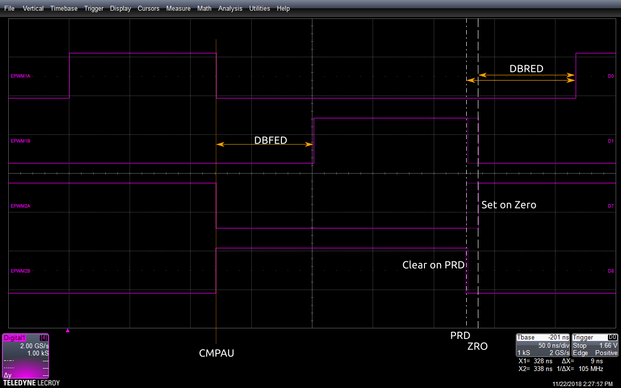
EALLOW;
CpuSysRegs.PCLKCR0.bit.TBCLKSYNC = 0;   // Disable TBCLK within the EPWM
EDIS;

EPwm1Regs.TBCTL.bit.PRDLD = TB_SHADOW;  // set Shadow load
EPwm1Regs.TBPRD = period;
EPwm1Regs.TBPRDHR = (uint16_t)128 << 8;
EPwm1Regs.CMPA.bit.CMPA = period / 2;   // set duty 50% initially
EPwm1Regs.CMPA.bit.CMPAHR = ((uint16_t)0 << 8);   // initialize HRPWM extension
EPwm1Regs.CMPB.bit.CMPB = period / 2;   // set duty 50% initially
EPwm1Regs.CMPB.all |= 0;
EPwm1Regs.TBPHS.all = 0;
EPwm1Regs.TBCTR = 0;

EPwm1Regs.TBCTL.bit.CTRMODE = TB_COUNT_UP;        // Select up count mode
EPwm1Regs.TBCTL.bit.SYNCOSEL = TB_SYNC_DISABLE;
EPwm1Regs.TBCTL.bit.HSPCLKDIV = TB_DIV1;
EPwm1Regs.TBCTL.bit.CLKDIV = TB_DIV1;             // TBCLK = SYSCLKOUT
EPwm1Regs.TBCTL.bit.FREE_SOFT = 11;

EPwm1Regs.CMPCTL.bit.LOADAMODE = CC_CTR_PRD;
EPwm1Regs.CMPCTL.bit.LOADBMODE = CC_CTR_PRD;
EPwm1Regs.CMPCTL.bit.SHDWAMODE = CC_SHADOW;
EPwm1Regs.CMPCTL.bit.SHDWBMODE = CC_SHADOW;

EPwm1Regs.AQCTLA.bit.ZRO = AQ_SET;
EPwm1Regs.AQCTLA.bit.CAU = AQ_CLEAR;
EPwm1Regs.AQCTLB.bit.ZRO = AQ_SET;
EPwm1Regs.AQCTLB.bit.CBU = AQ_CLEAR;

EALLOW;
EPwm1Regs.HRCNFG.all = 0x0;
EPwm1Regs.HRCNFG.bit.EDGMODE = HR_BEP;          // MEP control on both edges.
EPwm1Regs.HRCNFG.bit.CTLMODE = HR_CMP;          // CMPAHR and TBPRDHR HR control.
EPwm1Regs.HRCNFG.bit.HRLOAD = HR_CTR_ZERO_PRD;  // load on CTR = 0 and CTR = TBPRD
EPwm1Regs.HRCNFG.bit.EDGMODEB = HR_BEP;         // MEP control on both edges
EPwm1Regs.HRCNFG.bit.CTLMODEB = HR_CMP;         // CMPBHR and TBPRDHR HR control
EPwm1Regs.HRCNFG.bit.HRLOADB = HR_CTR_ZERO_PRD; // load on CTR = 0 and CTR = TBPRD
EPwm1Regs.HRCNFG.bit.AUTOCONV = 1;        // Enable autoconversion for HR period

EPwm1Regs.HRPCTL.bit.TBPHSHRLOADE = 1;    // Enable TBPHSHR sync
EPwm1Regs.HRPCTL.bit.HRPE = 1;            // Turn on high-resolution period control.

EPwm1Regs.TBCTL.bit.PHSEN = 1;


CpuSysRegs.PCLKCR0.bit.TBCLKSYNC = 1;      // Enable TBCLK within the EPWM
EPwm1Regs.TBCTL.bit.SWFSYNC = 1;          // Synchronize high resolution phase to start HR period
EDIS;
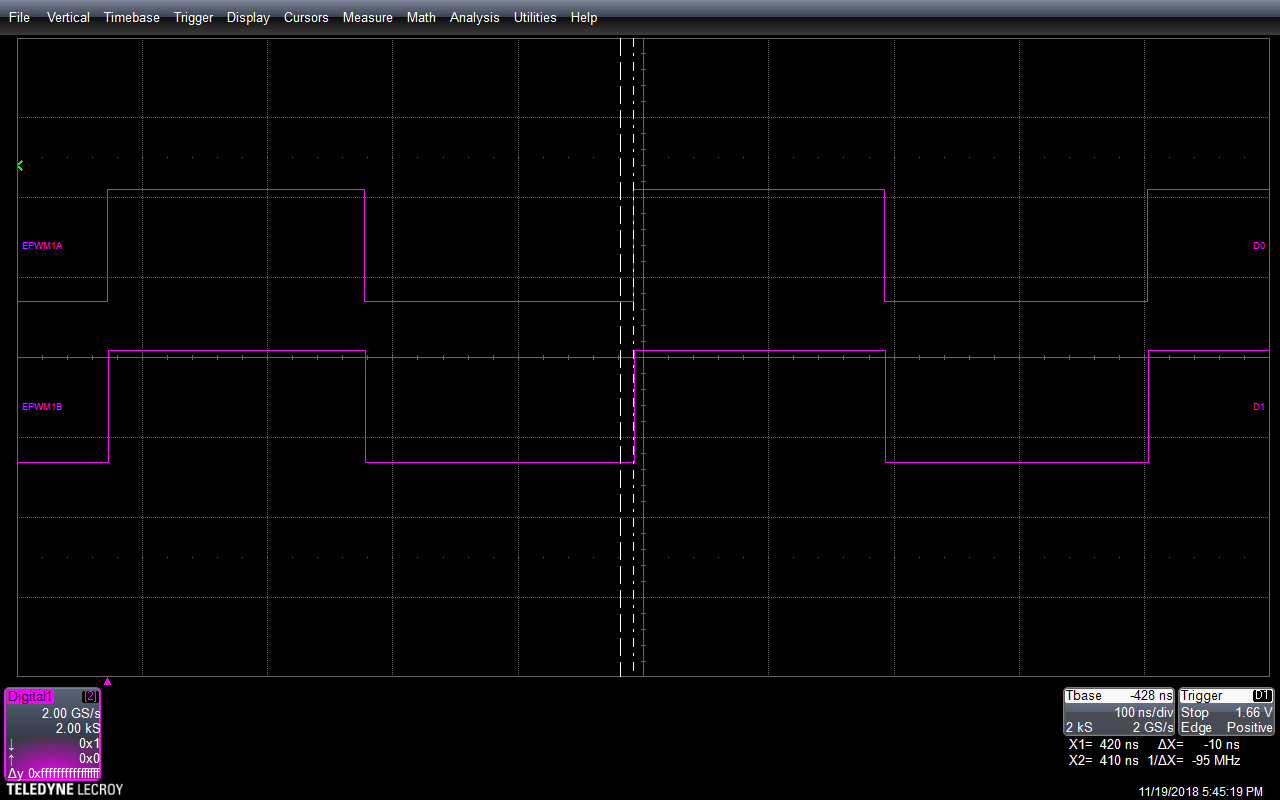
For demonstration I set period to 40 and PRDHR to 128 (see code above). In the scope screenshoots you can see, that the second pulse jitters by 10ns (1Sysclk). The third pulse stay stabil. By other values the following pulses jitter also.

Can anybody help me with this? Is in the config a fault?
Is there a restriction by using HR dutycycle and period control at the same time? I found in the Reference Manual only Duty Cycle Range Limitation, but this is not concern this here (CMPx is period/2).
Thanks