This thread has been locked.
If you have a related question, please click the "Ask a related question" button in the top right corner. The newly created question will be automatically linked to this question.
Tool/software: Code Composer Studio
Hi,
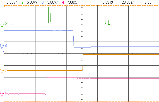
I observe that when I'm loading the CMPA register with the desired variable for EPWM comparison, the delay in the falling edge is more than that in the rising edge. The pink line is the variable that I'm feeding to CMP register, it's low value is 0 and high is 1.2*TBPRD. Hence I expect the output waveform of EPWM (yellow) to closely follow the input pink waveform, which I'm displaying using a DAC. The green pulses indicate the zero crossings of TBCTR up down counter, being displayed as the EPWM output by comparing against 0.1*TBPRD.
(please ignore the cursors (dotted vertical lines) in the following figures, by 'delay' I mean the lag between the pink and the yellow waveforms rising/falling')
Rising edge: delay less than one period of TBCTR triangle
Falling edge: delay is one period of TBCTR triangle
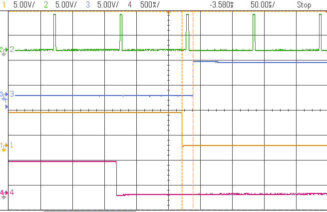
Due to this increased delay in the falling pulse in comparison to that of the rising pulse, the width of the output pulses is greater than that of the input variable pulse. This is the case irrespective of whether the shadow is enabled or not.
How do I minimize the delay of the EPWM output pulses, so that the lag between the pink and yellow waveforms is minimized?
How do I ensure that the delay is the same for both edges, so that the pulse widths are unaffected?
Thanks
Archana
Hi Pramod,
I don't think the delay is due to the deadband. I've set 80 for both FED and RED. These are my settings:
EPwm1Regs.TBPRD = 3901; EPwm1Regs.TBCTL.bit.HSPCLKDIV = 0x2; EPwm1Regs.TBCTL.bit.CLKDIV = 0x2; EPwm1Regs.TBPHS.half.TBPHS = 0; EPwm1Regs.TBCTL.bit.CTRMODE = TB_COUNT_UPDOWN; EPwm1Regs.TBCTL.bit.PHSEN = TB_DISABLE; // Master module EPwm1Regs.TBCTL.bit.PRDLD = TB_SHADOW; EPwm1Regs.TBCTL.bit.SYNCOSEL = TB_CTR_ZERO; // Sync down-stream module EPwm1Regs.CMPCTL.bit.SHDWAMODE = 0;//SHADOW enabled EPwm1Regs.CMPCTL.bit.SHDWBMODE = 0; EPwm1Regs.CMPCTL.bit.LOADAMODE = CC_CTR_ZERO; // load on CTR=Zero EPwm1Regs.CMPCTL.bit.LOADBMODE = CC_CTR_ZERO; // load on CTR=Zero EPwm1Regs.AQCTLA.bit.CAU = AQ_CLEAR; // set actions for EPWM1A AQ_CLEAR EPwm1Regs.AQCTLA.bit.CAD = AQ_SET; EPwm1Regs.DBCTL.bit.OUT_MODE = DB_FULL_ENABLE; // enable Dead-band module EPwm1Regs.DBCTL.bit.POLSEL = DB_ACTV_HIC; // Active Hi complementary EPwm1Regs.DBFED = 80; // FED = 50 TBCLKs EPwm1Regs.DBRED = 80; // RED = 50 TBCLKs
I update the value of a variable 's1a' during each iteration. This s1a is being displayed through DAC as the pink waveform. 's1a' toggles between 0 and 1.2
EPwm1Regs.CMPA.half.CMPA = s1a*EPwm1Regs.TBPRD;
Since the magnitude of s1a is greater than TBPRD, the output of comparison with TBCTR will also be a square waveform, identical in shape to s1a. A little bit of delay would be tolerable. For me, the issue is that the output pulses have different width from the input s1a pulses due to the unequal rise and fall delays.
Yellow waveform is the output at the EPWM pin.
Would you please elaborate on why you said the FED and RED would not take effect? How can I ensure that they take effect?
1. The rising edge and falling edge delay is fixed in terms of TBPRD cycles. When shadow is disabled (1), the delays are as follows:
Rising edge: about half the up-down period of TBCTR
Falling edge: about one period of TBCTR up-down
2. The yellow output is ePWM1A
3. The delay is observed irrespective of the rate of change of s1a value. I've attached a project, in which the 'archana_EPWM_delay.c' code contains s1a toggling during every iteration of the code (iteration forced by TBCTR zero crossing). Also 's1a' is being displayed through DAC channel D. Zero crossings of TBCTR are being viewed through ePWM2A (green pulses).archana_EPWM_delay.rar