


Part Number: TMS320F28020
Hi Expert,
Customer has met the DBRED load issue as the below shown.
In the below figure,
The green EPWM3A and blue EPWM2A are synchronous and have same TBPRD configuration, both are set 1 at ZERO moment and set 0 at CMPA up edge.
The differences of the two PWMs are the blue EPWM2A could be load DBRED value while the green EPWM3A with no DB register setting; the blue EPWM2A is set low when CBC event occurs while there is no action on green EPWM3A .
The purple wave will be low when the "EPwm1Regs.TZFLG.bit.CBC==1".
The yellow pulse means the CBC event which could trigger EPWM3A occur at that moment. The frequency of CBC event is 20kHz, while the ISR frequency is 27kHz.
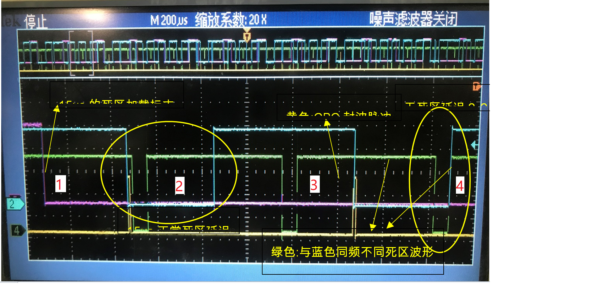
As the picture shown, the EPWM2A is separated into 4 TB periods
The working conditions are:
# At the first period of EPWM2A, when the yellow CBC event pulse occur, the blue EPWM3A comes down.
# At the second period, the blue EPWM3A could load the DBRED rightly, however the CMPA value begins to be 1800 which is more than TBPRD=1333.
# At the third period, the EPWM3A keep high for the CMPA>TBPRD, and to be low when CBC event occur,
# At the 4th period, with "EPwm1Regs.TZFLG.bit.CBC==1" , the EPWM3A just set 1 at zero moment, but no DBRED delay
What we confused is that why the DBRED could not de loaded in 4th period, is this because the CMPA>TBPRD?
Is there a execution sequence of AQ, DB, TZ in time?
------------------------------------------------------------------------------------------------
The below is the PWM configuration code.
The below is the PWM configuration code


// immediately load software force options

         EPwm2Regs.AQSFRC.bit.RLDCSF = CC_LD_DISABLE;

         //PWM_DISABLE

         EPwm2Regs.AQCSFRC.bit.CSFA =  AQ_CLEAR;

         EPwm2Regs.AQCSFRC.bit.CSFB =  AQ_CLEAR;

         EPwm2Regs.TBCTL.bit.CTRMODE = TB_COUNT_UP;

         EPwm2Regs.TBCTL.bit.PHSEN = TB_ENABLE; // !!!!!

         EPwm2Regs.TBPHS.half.TBPHS=0;

         EPwm2Regs.TBCTL.bit.PRDLD = TB_SHADOW;

        EPwm2Regs.TBCTL.bit.SYNCOSEL=TB_CTR_ZERO;

        EPwm2Regs.TBCTL.bit.SWFSYNC = 0;//??????--???

        EPwm2Regs.TBCTL.bit.HSPCLKDIV = TB_DIV1;

         EPwm2Regs.TBCTL.bit.CLKDIV = TB_DIV1;

         EPwm2Regs.TBCTL.bit.PHSDIR = 0;//??????

        EPwm2Regs.TBCTL.bit.FREE_SOFT = 3;//???????

         // Period register -- Setup 50 kHz PWM frequency.

         EPwm2Regs.TBPRD =1333;

         // immediate write to write to compare register

         //CC:

         // setup compare for normal operation

         //??CC--interleave to PWM1/PWM2A ?? PWM2B

         EPwm2Regs.AQCTLA.bit.ZRO= AQ_SET;

         EPwm2Regs.AQCTLA.bit.CAU = AQ_CLEAR;

         EPwm2Regs.AQCTLB.bit.ZRO = AQ_SET;

         EPwm2Regs.AQCTLB.bit.CBU= AQ_CLEAR;

         // Compare register update control

         //CC????

         EPwm2Regs.CMPCTL.bit.LOADAMODE=CC_CTR_ZERO;

         EPwm2Regs.CMPCTL.bit.LOADBMODE=CC_CTR_ZERO;

         EPwm2Regs.CMPCTL.bit.SHDWAMODE = CC_SHADOW;

         EPwm2Regs.CMPCTL.bit.SHDWBMODE = CC_SHADOW;

         // set zero duty cycle

         //intial CMPA & CPMB

         //PWM_SET_ZERO_DUTY

         EPwm2Regs.CMPA.half.CMPA =600;

         EPwm2Regs.CMPB=133;

         EPwm2Regs.ETSEL.bit.INTEN=0;

         EPwm2Regs.TZCTL.bit.TZA = TZ_FORCE_LO;

         EPwm2Regs.TZCTL.bit.TZB = TZ_FORCE_LO;

 ---------------------------------------------------------------------------------------------------

// ISR Code section:

------------------------------------------------------------------------------------------------

         CmpMaster =1200;

         CmpSlave=1200;

         EPwm2Regs.TBPRD = 1333;

          if(EPwm1Regs.TZFLG.bit.CBC==1)  //????

         {

                 EALLOW;

                 EPwm1Regs.TZCLR.bit.CBC =1;

                 EDIS;

                 RS485_TX_DIS();               //?????????

       EPwm1Regs.CMPA.half.CMPA=1200; //30us

         EPwm2Regs.DBRED=(1200>>1);//15us????

         EPwm2Regs.CMPA.half.CMPA=1200+(1200>>1);         //????30us+15us=1800??40Mhz??

         }

         else

         {

         RS485_TX_EN();       //?????????

        EPwm1Regs.CMPA.half.CMPA=1200;

        EPwm2Regs.DBRED=0;

        EPwm2Regs.CMPA.half.CMPA=1200;

         }

         EPwm3Regs.TBPRD = 1333;

         EPwm3Regs.CMPA.half.CMPA = 1200;

         EPwm3Regs.DBRED=0;

         EPwm1Regs.AQCSFRC.bit.CSFA=AQ_NO_ACTION;

         EPwm2Regs.AQCSFRC.bit.CSFA=AQ_NO_ACTION;

         EPwm3Regs.AQCSFRC.bit.CSFA = AQ_NO_ACTION;
Thanks!
-Rayna


