This thread has been locked.

If you have a related question, please click the "Ask a related question" button in the top right corner. The newly created question will be automatically linked to this question.

LAUNCHXL-F28379D: Precise ADC value

Part Number: LAUNCHXL-F28379D

Hello,

I am using F28379D LaunchPad Development Kit for a project. I have design a simple circuit in the MATLAB simulink and run it in the F28379D LaunchPad Development Kit.
I am taking a AC signal input via ADC and providing it in DAC for output.
Both the input and output are seen in Oscilloscope.

There is a difference in Input signal and Output signal.
How can I make the output signal(DAC) more precise and close to Input signal (ADC)?
Which parameters of ADC and Simulink shall I change or modify in order to get a more precise output signal at DAC.

For easier understanding, I am providing some photos of the system.

Thanks in Advance.

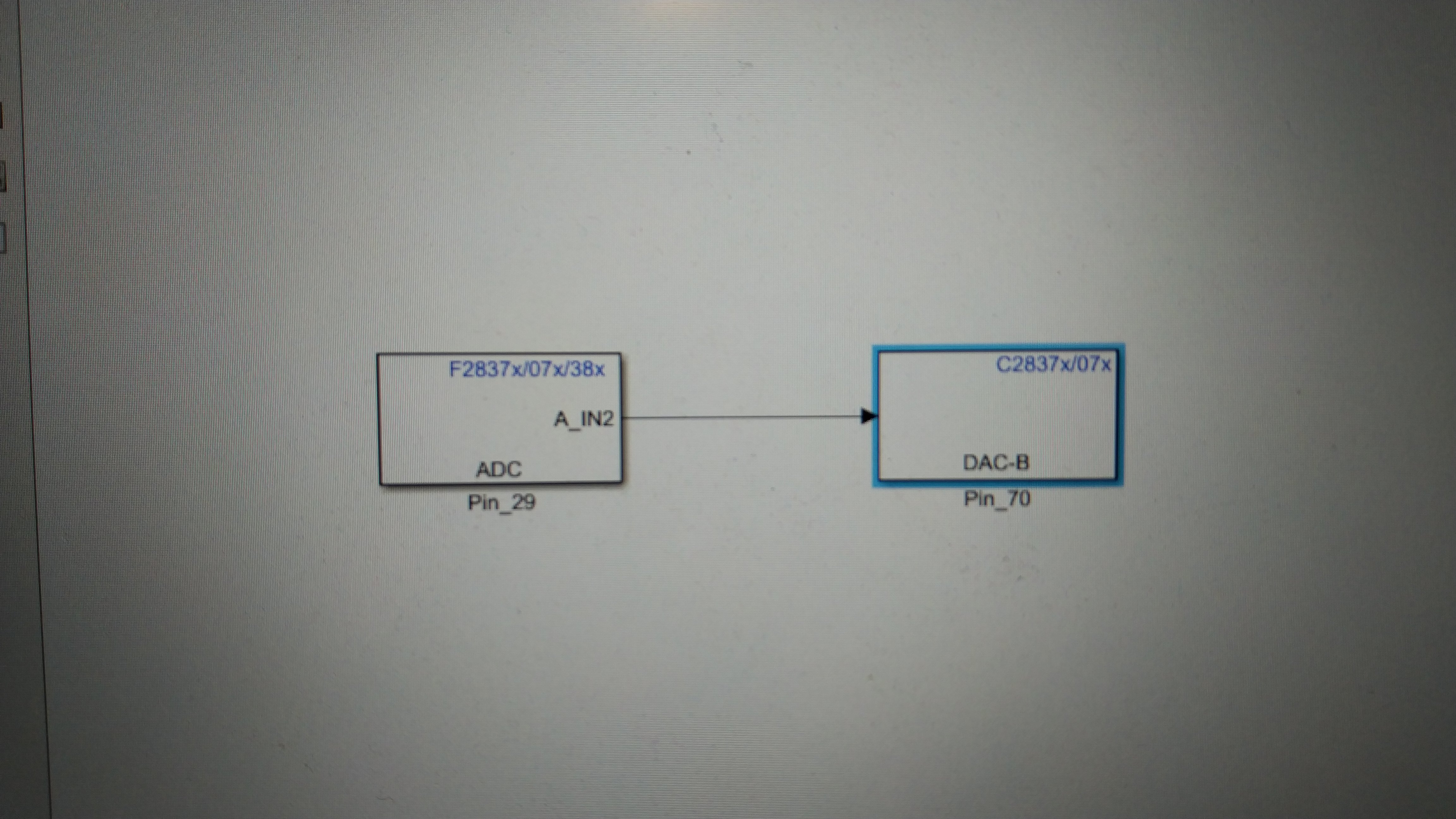
The above photo is of the design in simulink.

The above photo is of the Parameters of the ADC.

The above photo is of the Parameters of the model and LaunchPad.

The above photo is of the Input Signal at ADC.

 The above photo is of Output of DAC.

The above photo is both Input signal and Output signal.
I want to make the Yellow signal( Output of DAC) more precise to Green signal ( Input of ADC).

  • Hi Fahad,

    You might try the following:

    • Trigger ADC samples using ePWM or CPU timer instead of SW so that you get exactly evenly spaced samples (also CPU utilization will be reduced and sampling speed can therefore be increased)
    • Increase sample rate of the ADC: your output waveform is quite clearly quantized into discrete steps, but the ADC and the DAC are both capable of MSPS sampling and have resolutions higher than what your scope will be able to see
    • Read back the DAC output into the ADC and then compare with ADC samples from an appropriate earlier time to determine if there is gain/offset error
    • Oversample the ADC input
      •  If you keep increasing the ADC sampling speed this may result in the DAC output jumping around a bit due to sampled noise.  you can mitigate this by say sampling the ADC 8x faster than the DAC update rate and then averaging together those 8 ADC samples.  (Alternately, you could implement something like a moving average filter)
    • And also note that involving the CLA and/or DMA to reduce the CPU overhead will allow you to sample faster

    You also should take care with the physical setup of the input signal and the design of any signal conditioning circuits.  You will get vastly different performance out of the ADC if your input signal is jumpered in via a random unshielded wire directly to the ADC pin vs. using a shielded cable that is properly terminated and then locally buffering the signal on the PCB with a well designed op-amp based ADC driver circuit.  

  • Fahad,

    Does that resolves your issue? Can we close the thread now?