Other Parts Discussed in Thread: MSP430F5438A, MSP430F5437, MSP430F6638, MSP-FET, MSP430F5131, MSP430G2955
I'm new to programming microcontrollers and could use some help. I'm runing a Windows Vista Machine. Installed the IAR Kickstart v 5.2. I'm using the MSP-FET430UIF. I have a custom board that I'm trying to program via JTAG/SBW. When I hit the download and debug button, I get the following error message.
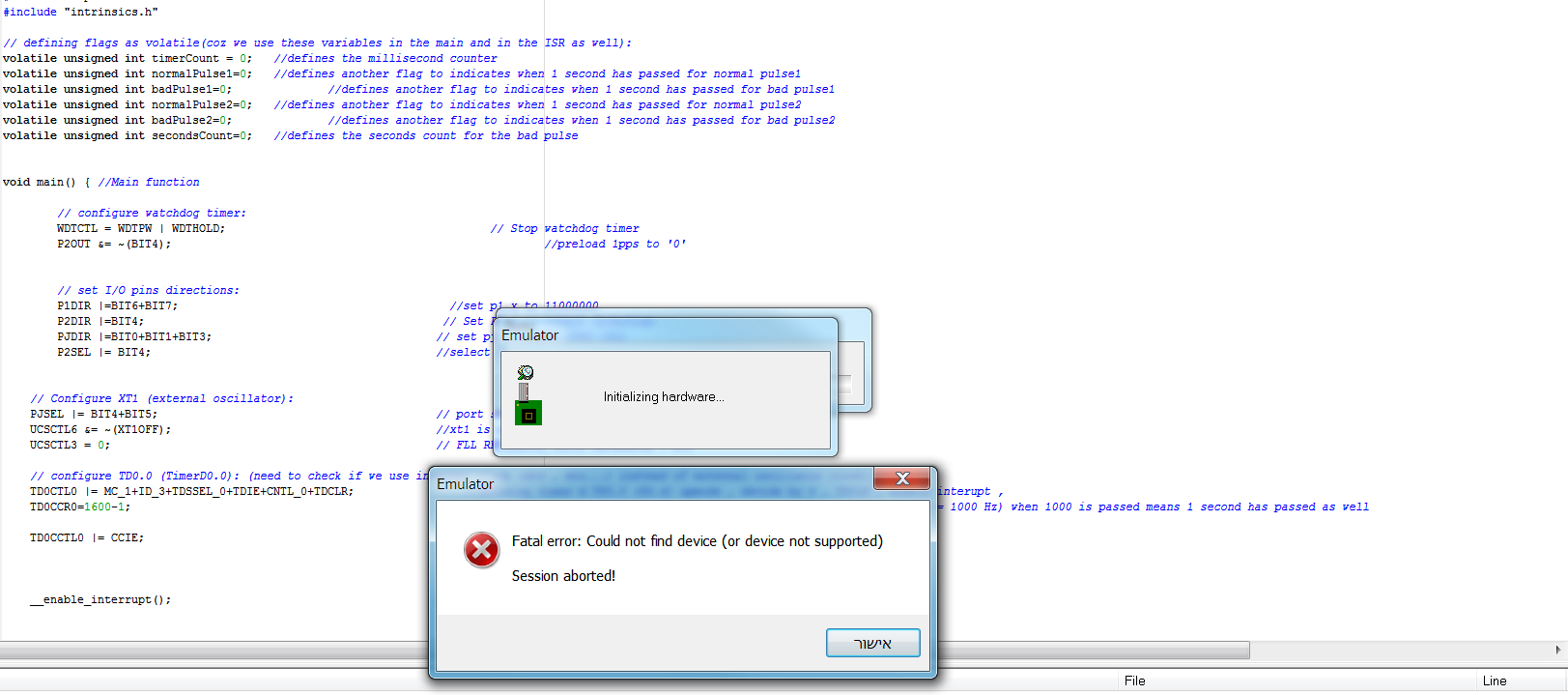
Fatal error: Could not find device (or device not supported) Session aborted!
Does that mean that I'm not communicating with my FET or does it mean that I'm not communicating with my target device?