This thread has been locked.

If you have a related question, please click the "Ask a related question" button in the top right corner. The newly created question will be automatically linked to this question.

EVM430-F6779: Not able to evaluate voltage and current peak values

Part Number: EVM430-F6779
Other Parts Discussed in Thread: MSP430F67791A, , MSP-ISO

Hello, 

  I am currently using msp430f67791a controller for evm430-f6779. I used the energy measurement design center (EMDC) to generate the ccs code for the controller according to my requirements. I gave current waveform to the phase c current channel for testing and the controller detected the digital values but the main array which calculates and stores the values is showing 0 in all elements.

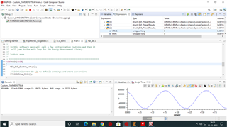
As shown in given image, controller is storing digital values but not able to evaluate the peak values of current.

What might be the issue?

Thanks

Avinash

  • Hi Avinash,

    Can you take pictures of the configurations you used in the EMDC? This might assist in seeing if the program was configured correctly.

    Regards,

    Luke

  • Hello,

    Following are my EMDC configurations:

    EMDC.zip

    Used default configurations as in EMDC 3 phase 50 Hz configurations except processor being msp430f67791a for my case.

    Thanks,

    Avinash

  • Hi Avinash,

    The example should work, especially if you're using the default configurations. 

    Have you taken a look at the application note for this device Implementation of a Three-Phase Electronic Watt-Hour Meter using MSP430F677x.

    Section 5 onwards should help with getting the Demo setup and running properly. The prior sections give some background information and technical details.

    I think there might have been a step missing in the setup that is causing this because otherwise it should be running fine. If anything the GUI should at least be displaying results as well.

    Once you take a look at that let me know if its still not showing data.

    Regards,

    Luke

  • Hello,

      Yes, I followed the instructions. 

    So I'm actually testing the board using code composer studio and measuring the voltage and current samples. I tried debugging this code which was generated using emdc configurations for msp430f67791a. Then to test the board I gave single phase voltage and currents to  Vc phase and Ic phase. To measure voltage samples I implemented SBW programming instead of JTAG to use MSP-ISO for isolation from high voltage ac channels.

    I gave AC voltage to Vc phase and I gave current Ic via a current sensor. The current sensor has an offset of Vcc/2 in its output but this was removed using op-amp differential circuit to remove Vcc/2 offset and obtain desired waveform b/w +930mV and -930mV.

    AC-DC converter provides 3.3 V to the msp430 controller as per board design.

    When I create a custom array in program to measure the current and voltage waveforms, it was able to measure the desired waveforms but was not able to show the results in EM_PHASE_RESULTS array which displays the calculated values of voltage and current.

    What might be the problem? I am not able to understand the issue and hence stuck with it?

    Also where does it calculate rms values in the program?

    Thanks

    Avinash

  • Hello,

       Instead of configuring for 3 phase in program I configured for 1 phase and reprogrammed the controller and now it is working. I was using the board for 1 phase to test it.

    Thanks

    Avinash

**Attention** This is a public forum