This thread has been locked.

If you have a related question, please click the "Ask a related question" button in the top right corner. The newly created question will be automatically linked to this question.

MSP430F6638: adc

Part Number: MSP430F6638

I have a 1V dc level applied to an op-amp buffer. The output is then feed through a 1kohm/1kohm voltage divider and then feed to to ADC0 input of the MSP430F3368. Instead of reading 0.5V I get a reading equivalent to 0.7V . When I look at the input on an oscilloscope I can see that the input is steady at 0.5V but when the ADC reading is taken the level rises to 0.7V making the input appear as a 200mV square wave with a 500mV offset. The frequency and period corresponds to and changes with the sample and hold time and sample frequency set on the ADC set up so is clearly related to the multiplexing of the ADC channel.

This seems too high to be the result of any leakage current. Can you explain where this is coming from and how to get rid of it.

I have also noticed that when the board is run in debug mode with the cable attached from CCS studio the input remains at 500mV, the square wave is not present and the ADC reading is as expected.
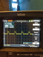
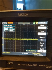
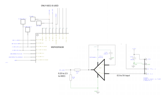
first image shows result with problem, 2nd show when board connected to CCS studio via jtag. N.B. since image taken the ADC12clk has been increased to 2MHz with no change. This looks like the ADC input is acting as a constant current source! how can this happen?

  • Hello David,

    Can you try your measurement again with the debugger physically connected but not engaged? AKA not debugging via CCS (or in free run mode). 

  • If you stop the debugger (red square) the ADC continues to run as expected with no squarewave. The square wave returns when the power is cycled - with or without the debugger connected

  • ok so two things happen when you have the debugger connected. When the internal debugger (EEM) is engaged (debug mode in CCS) everything in the device is slowed down as the debug process is intrusive. The other thing is purely hardware related as you get a coupling of the different system grounds (target vs debugger + PC).  This extra coupling could improve readings (better ground) or possibly do the opposite and introduce noise to the target system. So how does your ground look in your system? (assuming this is custom board). 

    Another thing to check is if you have any digital signals toggling close to the ADC input that couple be coupling to your signal. Typically this happens with higher frequency signal though, so I doubt its an issue here. Especially since it follows your ADC settings and nothing else.

    The last question is are the ADC register results reflect this change or are they showing the expected values/codes? SAR ADCs due affect the signal you are sampling as you are taking current to fill the sampling cap, which is why a buffer OA (like you have) is often used.

  • This is on our own product. We have the MSP430 on a CPU board and use different relay boards for various instrumentation.  I have an older version of code which runs with no problem. All the ADC12 registers are the same in the software.

    It looks like the ADC12 is behaving as a constant current source and when the input is selected the current flows out of the pin and appears across the resistor network on the input - although I can't understand how this is possible. It cannot be the charge on the sample and hold as it does not decay during the multiplexing!

    We did some testing without the resistors (so the input was driven by the op amp)and it resolved the problem, but we need the voltage divider as the output from the op amp can be 5V. Also I can make it work with the old code with the same hardware.

    There are no high frequency signals near by.

    When the squarewave is present the ADC readings are 150mV higher so the ADC is reading the top of the square wave.

  • the second channel of the ADC is not used on this product however I am sampling the port to match the working code. This pin A0 is effectively floating but if monitored I get a 2.5V square wave matching the time it is connected to the sample and hold circuit. 

    Again this does not happen with other software and is repeatable on other boards.

  • David,

    With this information, it leaves me to believe an issue with input impedance of your circuit to the ADC. Could you also try jumping the OpAmp and just having the voltage divider?

    What is your sample time set for the ADC? From the equation given in section 28.2.5.3  in the User Guide, filling in device parameters and an approximate input impedance of 1k ohm, it should be greater than 1.46us. 

**Attention** This is a public forum