


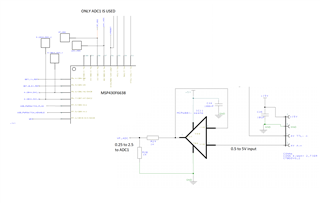
I have a 1V dc level applied to an op-amp buffer. The output is then feed through a 1kohm/1kohm voltage divider and then feed to to ADC0 input of the MSP430F3368. Instead of reading 0.5V I get a reading equivalent to 0.7V . When I look at the input on an oscilloscope I can see that the input is steady at 0.5V but when the ADC reading is taken the level rises to 0.7V making the input appear as a 200mV square wave with a 500mV offset. The frequency and period corresponds to and changes with the sample and hold time and sample frequency set on the ADC set up so is clearly related to the multiplexing of the ADC channel.
This seems too high to be the result of any leakage current. Can you explain where this is coming from and how to get rid of it.
I have also noticed that when the board is run in debug mode with the cable attached from CCS studio the input remains at 500mV, the square wave is not present and the ADC reading is as expected.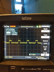
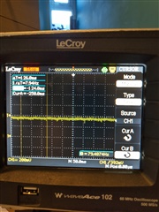
first image shows result with problem, 2nd show when board connected to CCS studio via jtag. N.B. since image taken the ADC12clk has been increased to 2MHz with no change. This looks like the ADC input is acting as a constant current source! how can this happen?
