This thread has been locked.

If you have a related question, please click the "Ask a related question" button in the top right corner. The newly created question will be automatically linked to this question.

EVM430-FR6047: About length measurement of transducers in the same pipe

Part Number: EVM430-FR6047

To whom it may concern

Two "EVM430-FR6047" were used to measure the transducer-to-transducer length of the same pipe.
The settings were written with exactly the same parameters by clicking "Request Update".
However, the results are 8.609 cm for ①and 8.430 cm for ②, a difference of about 0.2 cm. Is this a normal value? Is this amount of error possible for each microcontroller?
Or is there some other cause?

Confirmation_20220607.pdf

Best regards

  • Hi Masaki,

    This is the first time I have seen this.  Let me check with one of our USS experts.

  • Was the water temperature actually 22.40C for both measurements? A difference in temperature will affect Time of Flight/Speed of Sound, which in turn affects calculated distance.

  • Hi Masaki,

    I recall you were having trouble with one of your EVMs.  Did you ever replace it?

  • Thanks for the reply.
    The temperature is exactly the same.
    We have a thermometer right next to the meter to check. We fill the pipe with water and then check that the temperature has stabilized before taking the measurement.
    Is this a phenomenon that usually does not occur if the parameters are the same?
    Please let me know if there is any place or method I should check.

  • Hello Dennis

    Yes, I received a replacement and am using that one.

  • All the GUI is doing is measuring Absolute Time of Flight and multiplying it by the speed of sound of water at the temperature you specify. The 0.2cm would equate to ~1.3 uS difference between the two EVMs if 22.4C is indeed the fluid temperature.

    Go into the waveforms tab and run both EVMs for a few seconds at least and compare the Absolute TOF values obtained with each EVM. If the GUI is reporting a difference in distance when you calibrate, there should be a change in Absolute TOF as well. It may also be helpful to compare an ADC Capture with each EVM to see where the waveform is in the window and find the peak amplitude.

    Absolute TOF is calculated primarily through a correct setting of Configuration->Advanced Parameters->Envelope Crossing Threshold. If the threshold is not set correctly, there could be cycle slips which would mean there would be an error in multiples of the test frequency. For example, a cycle slip at 1 MHz would show a DToF ~1 uS.

  • Hi Masaki,

    According to one of our USS experts:

    Speed of sound in water: 1500 m/s

    8.609 cm => 57.39 us

    8.430 cm => 56.20 us

    The reference length 8.511 cm => 56.74 us.

    The 0.18 cm difference corresponds to 1.19 us. This indicates they are locking to a different lobe with the 2 different boards. If they are using 1 MHz transducers, each lobe is separated by 1 us. It is possible that the “Envelope crossing threshold” they are using might not be correct for the transducers and pipe combination. The threshold is set in the “Advanced Parameters” panel. 

    Please refer to section 4.2.2, Figure 4-5 of the Quick start guide at https://www.ti.com/lit/pdf/slau810.

  • Hi Dennis

    I understand about the possibility of locking to different lobes.
    I have described my approach to thresholds in question 1 of the attached document. Please confirm that my approach to setting the threshold is correct.

    I also have a question about ACDcapture when water is flowing. As I mentioned in question 2 of the attached document, when water is flowing, there is a difference in the peak value between UP and DOWN. Is this a correct phenomenon?

    Please answer.

    About the value of Envelope Crossing Threshold.pdf

  • Hi Masaki,

    The amplitude of the waveform from shouldn't matter.

    From slaa889a

  • Hello Dennis

    Thank you for contacting us.
    I understand that the difference in amplitude magnitude at high flow rates does not affect the flow measurement.

    Am I correct in the way I described in question 1 regarding the "Envelope Crossing Threshold" setting value?

  • Hi Masaki,

    I apologize for missing a response to your question #1.  Ans - Yes, based on the waveform you show, your method is correct.  A value of 10 (10%) is good.

  • Thank you for your response.
    Do I need to set different values for each meter in the "configuration" such as threshold values? Or, if we are using the same design and the same model number of sensor, is it OK to fix them to the average value of each meter, etc.?

  • Hi Masaki,

    One threshold value can be used for all, depending on how closely manufactured each transducers is.  Let me check if there is a preferred method to determine optimal setting.

  • We are currently using multiple sensors and Pipe to get ADCcapture. From those values, we are checking the variation of the peak and the first lobe. I am thinking of taking the process of determining the threshold value from the acquired variation data, is this a good idea?
    Please let me know if there are any problems that can be anticipated.

    I would like to check something else besides the issue of the threshold value. Should I ask a separate question in that case? Can I continue to reply here?

  • Hi Masaki,

    I asked our USS expert and he says the following:

    Usually, they do not need to set for each unit in production. The water meter transducer should be produced in a mature production line. The differences between transducer can be controlled in a very low level in big transducer manufactures.

    However, if they do need to calculate the threshold for each unit. Customer would do an impedance test for each transducer and categories them based on the impedance value. And get a proper threshold configuration and other settings for each category. So they would not need to set for each meter.

    Regarding a new question, you can continue to reply here.

  • Thank you for your answer Dennis.

    I have included additional questions in the additional PDF.
    Please check it out

    .About Signal Sampling Frequency.pdf

  • Hi Dennis.
    I have two additional questions.
    1, Do you have any documents that summarize trouble cases and design defects that may occur? (like DFMEA documents).
    We would like to confirm in advance possible problems that may occur in the future as we proceed with the enclosure and board design.

    2, Do you have any recommendations on how to evaluate and verify the reliability of ultrasonic water meters? In particular, we do not have much in-house expertise in testing the performance of ultrasonic sensors, so we would appreciate it if you could provide us with some guidance.
    We would like to use it to measure tap water, and would like to evaluate it to prove that it can make stable measurements for 9 to 10 years.
    Please confirm this in conjunction with the previous question.

  • Hi Masaki,

    Let me check with our USS expert on both recent postings.

  • We look forward to hearing from you.

    I have one more question.
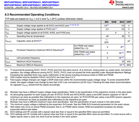
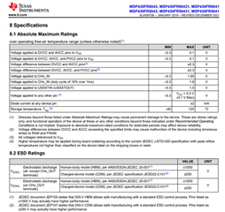
    Regarding the voltage, when I check the specifications below, it says that a voltage difference of ±0.3V or more between AVCC, DVCC, and PVCC may cause a malfunction.

    If we have separate power supplies at PVCC, ADCC, and DVCC, and the voltage of one of the batteries drops over time, is there a possibility that the ultrasonic waveform will be affected and the position of the wave across the threshold will change?

    If it will take time to confirm, please answer after the earlier question.

  • How is the progress on the question you are asking?
    I have an internal meeting tomorrow evening, so if you have any questions that you can answer, even one, I would appreciate it if you could contact me first.
    I apologize for the inconvenience.

  • Hi Masaki,

    I apologize for the delay in my response.  Unfortunately our USS expert is located in Shanghai and it can take 1 to 2 days to get a response.  He has responded:

    1. We would suggest the customer to use 3600kHz sampling frequency for 1MHz transducer. We have seen an issue on one customer before using 4MHz. It can cause a harmonic issue on the ADC capture.
    “Based on the ADC captures we’ve analyzed, we anticipate that we will find a harmonic at 3MHz which is varying over this time period in amplitude.  At 4MSPS, this harmonic would mirror into the 1MHz resonant frequency of the transducer – whereas at 3.6MSPS, this harmonic would mirror into a different frequency.”


    2. The shape of the ADC capture would not affect the algorithm. Because we will interpolate the ADC data to find the peak value of each lobe and then analyze those. The interpolated data is not going to have big differences between the 3600kHz sampling frequency or the 4000kHz. 


    3. The sampling frequency parameter will affect the HSPLL setting. With 3600kHz, the HSPLL is at 72MHz. And with 4000kHz, the HSPLL is at 80MHz. The ASQ is controlling the entire measurement sequence. And it is sourced by the HSPLL clock. So the starting point can be changed by different sampling frequency configuration. 


    4. The advantage of using a higher sampling frequency is that it will give you a smaller STD value. However, it will increase the chance of getting a cycle slip on the absTOF/dTOF result. The sampling frequency is preferred to set as 3.6 times of the transducer frequency in our library. 


    5. About the DFMEA and manufacturing. Well, some situations they might need to consider on a system level. Like, air bubbles in the pipe, scale incrustation on the transducer and temperature. And there is no standard protocol to solve these issues. Some customer will detect these errors in the software and send out the error message via NBIOT and waiting for a repair. And some customer will focus on the hardware to avoid these issues. 

    Regarding your question about PVCC, AVCC, DVCC, it is difficult to say what the failure mode might be.  I'll assume it is PVCC that is is dependent on the battery voltage - can you confirm?  What is the battery voltage range over time.  The AVCC and DVCC supplies are powered from an LDO or other source?  What is their voltage?

  • Hi Dennis.

    Thank you for your reply.
    Sorry for rushing you through this.

    I would like to ask about number 3, what is ASQ?

    I don't really understand the phenomenon of cycle slip in number 4 properly. Do you have any easy-to-understand material on this?

    Regarding number 5, I am not in charge of board design, so I do not know the details. In the schematic I am currently considering, there is a regulator in front of the PVCC and it is 2.7V, while the DVCC and AVCC are 3V directly from the battery. The specification "AbsoluteMaximumRaatings" states that the voltage difference between the DVCC, AVCC, and PVCC terminals is ±0.3.
    Is the current voltage difference of +/-0.3 a problem? Also, if the battery voltage were to drop to, say, 2.3V and the voltage difference were to drop to -0.4V, would this be a problem?
    If it is a problem, I am wondering if I should consider running everything through the same regulator.

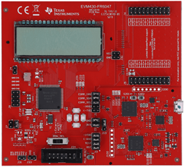
    Also, I would like to get analog waveforms from my current evaluation board using an oscilloscope or similar, any suggestions? (what pins should I connect, etc.)

  • Hi Masaki,

    ASQ stands for acquisition sequencer.  Information can be found in the user's guide, page 463.

    There isn't a lot of information about cycle slip, but can be explained by this illustration.  Basically, the absTOF uses the peak lobe closest to the threshold value.  In the illustration on the left, this is the first lobe.  If the threshold is set close the first lobe peak, then what can happen in high flow rates, the waveform can change slightly and the threshold can be closer to the second lobe peak as shown on the right.  The distance between the lobes is one cycle.  So if during a measurement the absTOF changes suddenly, this is usually due to a cycle slip.

    Regarding the power supplies, if PVCC comes from a 2.7v LDO and AVCC, DVCC come from battery, then yes, AVCC, DVCC can only be as low as 2.4v.  But if battery drops to 2.4v, how is it possible LDO (low drop-out regulator) can produce 2.7v??  What is the source for input to the LDO?  The recommendation is to tie all three supplies together. 

    To measure signals with the scope you can probe the CHx_OUT and CHx_IN pins.

  • Hello Dennis
    Thanks for contacting me.

    I understand about the ASQ. Thank you very much.

    Regarding cycle slip, in your answer to #4, you said that if the value of Signal Sampling Frequenc is high, the possibility of cycle slip will be higher.

    However, when I check the diagram you provided, I feel that this phenomenon occurs regardless of the value of Signal Sampling Frequenc.

    What causes cycle slips when the value of Signal Sampling Frequenc is high?

    Which pins are CHx_OUT and CHx_IN pins in the picture below?

  • Yes, it is possible for cycle slip to occur even when using recommended sampling frequency, depending of other contributing factors, such as very high flow rates or the threshold level.  Our expert was simply pointing out that there is a chance this can occur if using higher sampling rates.

    I assume you are using 1MHz transducers, so 3600 would be recommended sample rate.

    Regarding the signal connections, here is the schematic and PCB locations where you can probe both inputs and outputs.

  • Please let us know if you know the factors that make cycle slip more likely to occur when higher sampling rates are used. Based on past cases that your company is aware of, does this mean that a higher value of Signal Sampling Frequency is more likely to cause this?
    Also, we are currently considering using a 1MHz transducer. Is 1MHz common for small to medium diameter (13mm to 40mm) water meters?
    What are the reasons why 1MHz is chosen?

    Also, what are the possible advantages and disadvantages of raising the frequency to 2MHz?

    I understand about the location of the probe. Thank you very much.

  • Hi Masaki,

    I apologize for the delay in my response. 

    A higher sampling frequency is not always likely to cause cycle slippage, rather it is one possible reason.  Unless you have a specific reason to sample faster, I would use 3600kHz and look for other possible causes of the cycle slippage if they continue to occur. Other factors for cycle slip include transducers with side-band frequencies whose energy is close to the peak frequency and high flow rates.

    Transducers with a wide Q or wide resonant frequency may have side-band frequencies with high enough energy to interfere with the peak frequency.  On method to resolve this might be add some filtering in HW to help suppress the side-band frequencies, or work with the transducer manufacturer to use transducers with a narrower resonant frequency.

    Also, if using a 1MHz transducer, make sure that the correct transducer excitation frequency is selected. For a nominal frequency of 1 MHz, using an excitation frequency that is 100 kHz away from the correct frequency can cause as
    much as 15 dB of attenuation in the signal amplitude, and the frequency response can also be significantly worse.

    For cycle slip caused by high flow rates, you may have to consider modifying the size of your pipe to reduce the velocity.

    BTW - In case you have not seen this information, you might find additional answers here -> link.  Seach for "cycle slips".

    A 1MHz transducer is very common in the industry. My understanding is 1MHz frequency propagates well in water.  2MHz is used because they enable smaller form factors for the sensing pipe.  In terms of performance, no, I'm now are of any advantage when using a 2MHz transducer.

    Check the FAQ on ultrasonic sensing technology regarding other advantages or reasons for using 1MHz vs. 2MHz.

  • Thank you for your answer. What parameters in USS need to be adjusted to set the correct excitation frequency?
    Should I check FrequencySweep and adjust the Transmit frequency F1 value?
    Or do I also need to adjust parameters that cannot be changed by USS alone?

**Attention** This is a public forum