- Ask a related questionWhat is a related question?A related question is a question created from another question. When the related question is created, it will be automatically linked to the original question.
This thread has been locked.
If you have a related question, please click the "Ask a related question" button in the top right corner. The newly created question will be automatically linked to this question.
Hello everyone,
I've run into a problem configuring the clock system for using an external 8MHz crystal. I'm using the 64VQFN variant of the chip (MSP430FR5043IRGCT).
The crystal oscillator seems to be working fine, when measuring with an oscilloscope I get a clean 8 MHz sine wave from the crystal at the HFXIN pin.
However, when I set the pin P3.3 to output MCLK, I get a square wave with a frequency of 4.75 MHz (same for P3.4 and output SMCLK).
I've configured the CS to use HFXT as source for MCLK and SMCLK with a divider of 1, maximum drive strength. The bypass capacitors I use are 14 pF each.
Even if I only configure the CS module, and don't use any other peripherals, the MCLK/SMCLK are at 4.75 MHz.
Below is the code I use for testing the CS module:
#include <msp430.h>
#include <stdint.h>


/**
 * main.c
 */
int main(void)
{
    uint16_t i = 0;                                 // Variable for counting down in fault flag clearing loop...

	WDTCTL = WDTPW | WDTHOLD;	                    // stop watchdog timer

	PM5CTL0 &= ~(uint16_t)LOCKLPM5;                 // unlock port pins

	// initialize external 8 MHz crystal

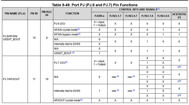
    PJSEL0 |= (1 << 6);                             // configure PJ.6 / PJ.7 to be used as HFXTIN/ HFXTOUT
    PJSEL1 &= ~(1 << 6);

    CSCTL0_H = 0xA5U;                               // Write key to key register, unlock CS module registers


    CSCTL1 &= (uint16_t)0x0000U;                    // clear register, we don't need the DCO
    CSCTL2 = (uint16_t)0x0155U;                     // Clock sources: ACLK = VLOCLK, SMCLK = HFXT, MCLK = HFXT
    CSCTL3 = (uint16_t)0x0000U;                     // All clock dividers = 1
    CSCTL4 = (uint16_t)0xC401U;                     // Max drive strength, no bypass, HFXT always on, HFFREQ > 4...8MHz, LFXT unconfigured / off, SMCLK on
    CSCTL5 = (uint16_t)0x00C0U;                     // Enable startup fault counters, clear HFXT/LFXT fault flags
    CSCTL6 = (uint16_t)0x000FU;

    do{                                             // Wait until HFXT fault flag is cleared.
        CSCTL5 &= ~((1 << 1) | 1);
        for(i = 0x1FFF; i > 0; i--);
    } while(CSCTL5 & HFXTOFFG);

    CSCTL0_H = 0xFF;                                // Write non-PW value to PW register => lock CS module registers


    // Configure P3.3 / P3.4 to output MCLK / SMCLK

    P3DIR |= (BIT3 | BIT4);

    P3SEL1 &= ~(BIT3 | BIT4);
    P3SEL0 |= (BIT3 | BIT4);

    // Do nothing...
    while(1) {

    }


	return 0;
}Hello Andreas,
Here is a code example for the MSP430FR5043 that supports an 8MHz crystal and outputs SMCLK. https://dev.ti.com/tirex/explore/node?node=A__AIKoHBH4YfzkN4eOHSTQCQ__msp430ware__IOGqZri__LATEST
Take a look and let me know if this helps. I do think that Keith is also pointing out a bug as well. I'd recommend using the "BITx" #defines like in the example, instead of manually shifting over the bits.
Thanks,
JD
Hello Keith,
thanks for your reply. According to the datasheet, only PJSEL1.6 and PJSEL0.6 have to be set, whereas PJSEL1.7 and PJSEL0.7 are "don't care" in case of HFXT operation; or am I misreading something in this table?

Hello JD,
thanks for the directions. I'll have a look at the code example and will let you know if that solved my issue.
Regards,
Andreas
JD,
I just tested the example code and it outputs an 8 MHz square wave SMCLK signal right away. This helps! Thank you.
Regards,
Andreas
Addition:
Regarding the example code, of course I have to set the LFXTOFF bit (and not clear it), as I only have an HF oscillator connected to the µC. Otherwise, the LFXTOFFG oscillator fault flag for the LFXT will never clear.
**Attention** This is a public forum