This thread has been locked.

If you have a related question, please click the "Ask a related question" button in the top right corner. The newly created question will be automatically linked to this question.

MSP430FR6047: MSP430FR6047: Design Center GUI Error: HID Bridge Connected - Waiting for Device.

Part Number: MSP430FR6047
Other Parts Discussed in Thread: UNIFLASH,


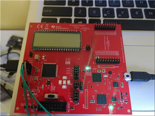
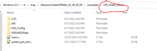
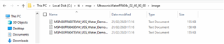
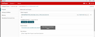
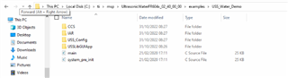
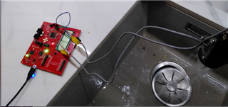
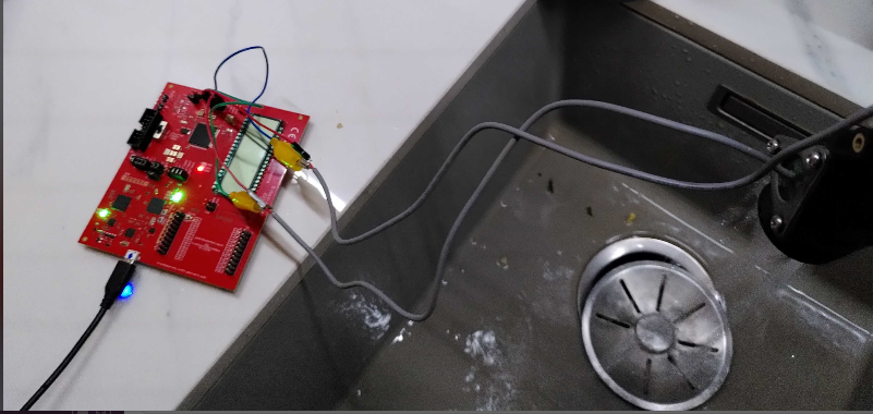
Hello, recently I have acquired a MSP430FR6047 board, and begin to follow the getting started guide of Ultrasonic Sensor Example , after the install the firmware of board with the uniflash tool, when I tried to use
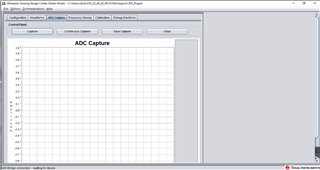
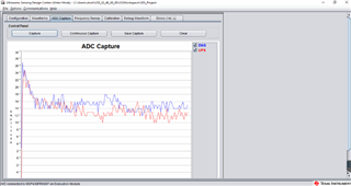
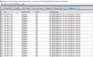
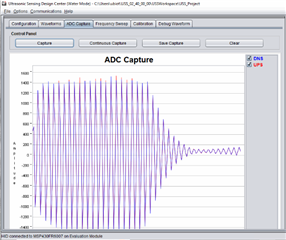
the design center in the GUI jointly with sensor , shows that the HID bridge is connected but It is waiting for device, i research and it seems that the GUI isn't be able to receive the parameters form the device.

Researching in the forum I found people who already had the same problem:

HID Bridge connected – waiting for device


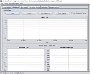
I tried to follow the solutions, such as updating the firmware (I have the last one that came out), and re-flashing it, but there came a time when the interface remained as stopped 

I am new to this and well, I also noticed that the D2.02 led is not shining, which is indicative that the HID bridge works but my pc detects when I use the uniflash that the board is connected.

I would like to know what is causing this behavior.

And I would be very grateful if you could help me.


  • Hi Erick,

    Do you have both transducers properly connected?

    Did you reflash the MSP430FR6047 with the water demo from the location shown below:

    If you don't see this directory on your PC, you need to download the USS_Water_Demo firmware from this LINK.

  • Hi, And thanks for assisting me, well I am using a .txt file as indicated in the guide


    And flash using the unisflash tool.


    but according with you answer yes,  I have this directory:


  • Hi Erick,

    Ok, just wanted to double check.

    If you have communications enabled, select the ADC capture tab and click the Capture button.  Do you see a waveform appear?

  • Hi Erick,

    Any luck?  I have tried this on my setup and when I first power the board it shows the same as yours, but if I click on the ADC capture or start the waveforms everything starts working.

  • hello sorry for the delay, ok I will try to apply that, and I will put the result here

  • Ok, I tried to use the ADC capture, but It doesn't show any reading


  • I tried to reconnect the device and the program was able to recognize the ADC reading,


    but now it gives me the error 126 of connection to the transducers, I am going to change the cable and make the connection again to test.


    On the other hand, the manual mentioned that I had to connect some jumpers, and that one of them intervened with the HID bridge, I would like to know how that connection is made because I do not understand how it is done and that may have to do with what happens .

  • Hi Erick,

    Ok, sounds like you are making some progress. 

    Regarding the error, you can look up that and at other error you might see in the USS Users Guide from inside the GUI.  Select Help>Topics from the main menu.  Then visit Error Handling section for a table of errors.  126 is "no signal detected in UP/DN stream channel.  Based on the capture of your ADC signal, you don't have the "Gap between pulse start and ADC capture" set properly.  To set this according to you pipe length, following the directions in section 4.2 of the Water Flow meter getting started guide, slau810.

    It appears from your very first picture from 3 days ago that all of your jumpers are correct, so you shouldn't need to do anything with them.  Here is the schematic, if that helps.

    Once you set the parameters (see the Configuration section in the USS User's guide), everything should start to work.

  • hello, thanks for stopping by, I was reading the guides, in this case I am using the audiowheel sensor recommended by the same gui to make the connection

    this is the model:

    HS0016-00 USS Audiowheel  

    because it should works with the same parameters that it indicates, I was also reading the section of errors and shows that this error is due to lack of water in the sensor or that it is poorly connected.

    This is my current connection, the red cables are the ones that go with the CH0 and CH1 connectors, and the other color ones are the ground ones, I assume that they must be connected that way or maybe I am connecting it wrong. This sensor only has 2 cables per transducer.


    I already tried putting it with water but I still get the error


  • Follow the guide the parameter should be 60 μs 

  • Hi Erick,

    Your Audiowell setup looks correct.  Referring to the Water Flow Meter User Guide, section 4.3, your ADC capture should look like figure 4.6.

    I would strongly recommend to do the initial parameter setup in static conditions (no water flow) The best way is to cap one end of the pipe, fill it with water slowly, then shake it to allow captured air bubbles to escape, then cap the open end of the pipe.  Note, you don't have to cap the open end, but you will need to hold the pipe up so water doesn't spill out while you dial in the correct parameters.

  • hello, thanks for the answer, that was the other thing that I also wanted to validate, that the problem could also be due to the way I have it installed, currently the pipe, which as you can see is with the water coming from a tap, it is say my question is that it must be sealed both sides? , and if that affects the path of the ultrasound?


  • Following your instructions, I sealed one of the ends of the tube and filled it with water and I was able to detect the ADC waveforms, comparing them with the previous one, this means that it is reading the signal from the transducer?

    I was also looking at the TOF, Delta TOF, and Volume Flow Rate graphs, and they no longer show a single straight line, so it was due to lack of water.


    I think what would be missing is to calibrate it to use a better frequency?

    On the other hand, notice that every time you empty the water, error 126 reappears, but it disappears when you refill the pipe. Does this mean that the sensor will not be able to capture the flow if there is no water?

    But what happens in the case of a larger pipe? If I have a 6-inch pipe in which the water is not necessarily going to fill its diameter one hundred percent vertically, does the ultrasonic sensor still make the measurement?, oh it has to be 100 percent full?.

  • Hi erick,

    Essentially, in order to use USS reliably you need to maintain a path between the two transducers that is 100% filled with water.  Any air can and will cause issues.  If the tube is only partially filled, the ultrasonic energy won't propagate and the upstream (UPS) and downstream (DNS) signals won't be received, causing error 126.

    Maintain 100% fill is generally not a problem for a pressurized pipe, such as in water pipe that comes into your house.  But for your application, the large pipe is not pressurized and simply carrying water, like the sewer pipes that leave your house.

    Let me ask, for the 6-inch pipe, how were you planning to mount the transducers?

  • Hello Dennis,

    Thank you so much for your detailed explanation. 

    Our vertical is groundwater metering for irrigation. Which means that in some cases we will dont have a path between the two transducers that is 100% filled with water. However it looks like we should be abe to handle the error 126. @ runtime simply assuming that there is not water extraction --> metering should be 0?? 

    Regarding the 6 inch. We are still on a early PoC desing phase. So no idea how we are going to install on 6, 8 or even 12" :-) Our guess is that transducer calibration for sure need to be tune since the ToF will be diff for higher diameter.  And we will need some industrial desing expert to check the internal manufacturing details. Metal 3D printing will help here!

    Best Regards,

    Erick Ilarraza

  • Hi Erick,

    Since the pipe is such a large diameter, you might want to consider using a "clamp-on transducer".  Here is an application note.  This works on PVC, but not very well through metal pipes.

  • Hello Dennis,

    Thanks a lot for your support. This note is quite useful. Just by chance did you know if that 3D printed source files are available? So we can try to reproduce the experiment.

    Best Regards,

  • Hi Erick,

    Here is a link to another E2E posting with regards to clamp on sensors.  Go all the way to the bottom and you will see links to the OpenSCAD file.

    If you are not familiar with OpenSCAD it can take a little getting used to.  It is a "parametric" driven  3D tool, which means you define the shapes by formulas and values.  It's quite fun once you get the hang of it.  Fortunately for you, all you need to do is change the values at the top of the file and re-render it.  That's what makes this so powerful.

    I'll include the code here for convenience.

    TRANSDUCER_RADIUS=8.4;
    PIPE_RADIUS=13.5;//13.5;
    CHANNEL_RADIUS=11;//11.5;
    PIPE_LENGTH=95;
    ULTRASONIC_ANGLE=50;
    ULTRASONIC_LENGTH=53;//53;
    
    difference(){
    union(){
    difference(){
        
        union(){
        	translate ([0, 0, -45]) 
            rotate([0, 0, 0])
       		cylinder (h = PIPE_LENGTH, r = PIPE_RADIUS);
                    
            translate ([-(PIPE_RADIUS+6.5), .1, -14.9]) 
            rotate([0, ULTRASONIC_ANGLE, 0])
       		cylinder (h = ULTRASONIC_LENGTH, r = TRANSDUCER_RADIUS+2);
        }
        
    union(){     
        	translate ([0, 0, -45]) 
            rotate([0, 0, 0])
       		cylinder (h = PIPE_LENGTH, r = CHANNEL_RADIUS);    
      
            translate ([-(PIPE_RADIUS+6.5), 0, -15]) 
            rotate([0, ULTRASONIC_ANGLE, 0])
       		cylinder (h = 150, r = TRANSDUCER_RADIUS);
        }
    }
    
    }
    union(){
            translate ([0, -PIPE_RADIUS, -45]) 
            rotate([0, 0, 0])
       		cube ([.5,PIPE_RADIUS*2,PIPE_LENGTH]);
    
        
    }
    }

  • Hello Dennis,

    Sorry for the delay. Now was able to test the tool. It is really super useful thank you so much. Just last check, may you please post again the link for the clamp on sensors?  I was unable to open it from previous post.

    Thanks a lot for your support.

    Best Regards

  • Sorry about that erick,

    LINK

  • Hello Dennis,

    Thank you so much for your support. We will try to reproduce the scenario! 

    Best Regards

**Attention** This is a public forum