Other Parts Discussed in Thread: MSP430FR2633, , CAPTIVATE-PGMR, TIDA-00343, TIDM-1021
Hi team,
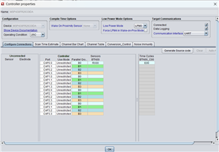
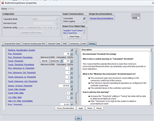
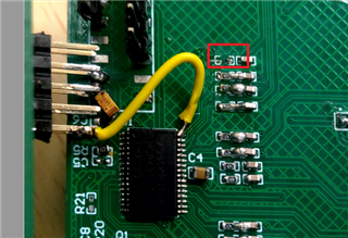
I am working on MSP430FR2633 MCU on a custom board using the debugger built in the MSP-EXP430F5529LP launchpad running in self capacitance mode. The touch isn't getting detected even after generating code
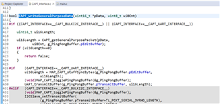
can anyone help me out with this. Below is the configuration code attached
#include "CAPT_UserConfig.h"
//*****************************************************************************
//
//! Captivate Element Definitions
//! All elements in this application are defined below.
//! Each element has 3 components:
//! 1) a raw count array (One index per freq. scanned) (uint16_t)
//! 2) a tuning array (One index per freq. scanned) (tCaptivateElementTuning)
//! 3) a element structure (tElement)
//
//*****************************************************************************
// Sensor: BTN00, Element: E00
uint16_t BTN00_E00_RawCnts[CAPT_SELF_FREQ_CNT];
tCaptivateElementTuning BTN00_E00_Tuning[CAPT_SELF_FREQ_CNT];
tElement BTN00_E00 =
{
.ui8RxPin = 0,
.ui8RxBlock = 0,
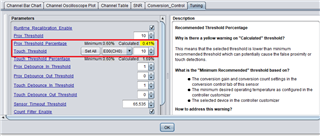
.ui8TouchThreshold = 60,
.pRawCount = BTN00_E00_RawCnts,
.pTuning = BTN00_E00_Tuning,
};
//*****************************************************************************
//
//! Captivate Time Cycle Definitions
//! All time cycles in this application are defined below. Time cycles are
//! groups of elements that are measured together in parallel in one time slot.
//! Each cycle has 2 components:
//! 1) an element pointer array to the member elements (tElement*)
//! 2) a cycle structure (tCycle)
//
//*****************************************************************************
// Time Cycle: BTN00_C00
tElement* BTN00_C00_Elements[1] =
{
&BTN00_E00,
};
tCycle BTN00_C00 =
{
.ui8NrOfElements = 1,
.pElements = BTN00_C00_Elements,
};
//*****************************************************************************
//
//! Captivate Sensor Definitions
//! All sensors in this application are defined below. Sensors are
//! groups of time cycles that utilize raw measurement data to create an
//! abstract sensor type, such as a button, slider, wheel, or prox sensor.
//! Each sensor has 3 components:
//! 1) a cycle pointer array to the member time cycles (tCycle*)
//! 2) a sensor-specific parameter structure (tGenericSensorParams)
//! 3) a sensor structure (tSensor)
//
//*****************************************************************************
//Sensor: BTN00
const tCycle* BTN00_Cycles[1] =
{
&BTN00_C00,
};
tButtonSensorParams BTN00_Params;
tSensor BTN00 =
{
// Basic Properties
.TypeOfSensor = eButtonGroup,
.SensingMethod = eSelf,
.DirectionOfInterest = eDOIDown,
.pvCallback = NULL,
.ui8NrOfCycles = 1,
.pCycle = BTN00_Cycles,
.pSensorParams = (tGenericSensorParams*)&BTN00_Params,
// Conversion Control Parameters
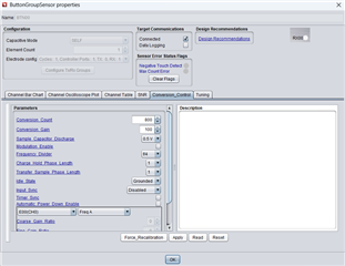
.ui16ConversionCount = 800,
.ui16ConversionGain = 100,
.ui8FreqDiv = 2,
.ui8ChargeLength = 0,
.ui8TransferLength = 0,
.bModEnable = true,
.ui8BiasControl = 3,
.bCsDischarge = true,
.bLpmControl = false,
.ui8InputSyncControl = 0,
.bTimerSyncControl = false,
.bIdleState = true,
// Tuning Parameters
.ui16ProxThreshold = 40,
.ui16NegativeTouchThreshold = 20,
.ui16ErrorThreshold = 8191,
.ui16TimeoutThreshold = 10000,
.ProxDbThreshold.DbIn = 1,
.ProxDbThreshold.DbOut = 0,
.TouchDbThreshold.DbIn = 2,
.TouchDbThreshold.DbOut = 1,
.bCountFilterEnable = false,
.ui8CntBeta = 1,
.bSensorHalt = false,
.bPTSensorHalt = true,
.bPTElementHalt = true,
.ui8LTABeta = 7,
.bReCalibrateEnable = true,
};
#if (CAPT_CONDUCTED_NOISE_IMMUNITY_ENABLE==true)
//*****************************************************************************
//
//! \var g_EMCConfig
//! This structure stores the EMC configuration for this application.
//
//*****************************************************************************
const tEMCConfig g_EMCConfig =
{
// Conversion Style
.selfModeConversionStyle = CAPT_SELF_MODE_CONVERSION_STYLE,
.projModeConversionStyle = CAPT_PROJ_MODE_CONVERSION_STYLE,
// Oversampling Style
.selfModeOversamplingStyle = CAPT_SELF_MODE_OVERSAMPLING_STYLE,
.projModeOversamplingStyle = CAPT_PROJ_MODE_OVERSAMPLING_STYLE,
// Jitter Filter Enable
.bJitterFilterEnable = true,
// Noise Thresholds and Calibration Noise Limits
.ui8NoiseThreshold = CAPT_NOISE_THRESHOLD,
.ui16CalibrationNoiseLimit = CAPT_CALIBRATION_NOISE_LIMIT,
.ui8CalibrationTestSampleSize = 8,
// Dynamic Threshold Adjustment Parameters
.bEnableDynamicThresholdAdjustment = CAPT_DYNAMIC_THRESHOLD_ADJUSTMENT,
.ui8MaxRelThreshAdj = 76,
.ui8NoiseLevelFilterEntryThresh = 40,
.ui8NoiseLevelFilterExitThresh = 0,
.ui8NoiseLevelFilterDown = 6,
.ui8NoiseLevelFilterUp = 1,
.coeffA = _IQ31(0.0065),
.coeffB = _IQ31(0.050)
};
#endif
//*****************************************************************************
//
//! \var g_pCaptivateSensorArray
//! This array allows for indexed access to any
//! sensor in the configuration.
//
//*****************************************************************************
tSensor* g_pCaptivateSensorArray[CAPT_SENSOR_COUNT] =
{
&BTN00,
};
//*****************************************************************************
//
//! \var g_uiApp
//! This structure stores the global settings for this application.
//
//*****************************************************************************
tCaptivateApplication g_uiApp =
{
.state = eUIActive,
.pSensorList = &g_pCaptivateSensorArray[0],
.ui8NrOfSensors = CAPT_SENSOR_COUNT,
.ui8AppLPM = CAPT_LOW_POWER_MODE,
.bElementDataTxEnable = true,
.bSensorDataTxEnable = true,
.ui16ActiveModeScanPeriod = 33,
.ui16WakeOnProxModeScanPeriod = 100,
.ui16InactivityTimeout = 32,
.ui8WakeupInterval = 5,
};