Other Parts Discussed in Thread: EVM430-FR6043
Hello,
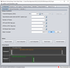
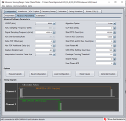
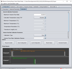
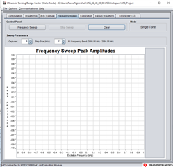
i have a problem with the Board EVM430-FR6043. and namly i tested the Board with 1MHz sensor and it worked well. then i used 2Mhz sensor, and the signal was different by different flow. and ofcourse the TOF was not correct. see the images for better understanding.
is there any way to solve this? i checked the signal with Oscilloscope on both channel and ther was the same.
bei 1000ml/s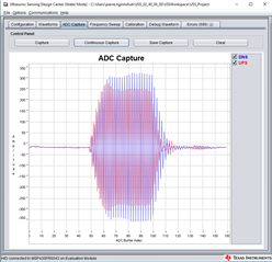
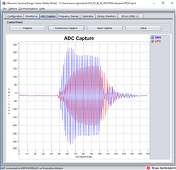
bei 450ml/s
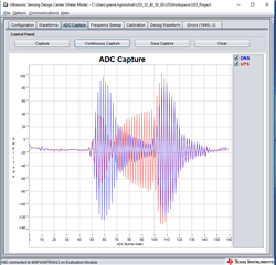
and bei 60ml/s
best Regards
Pierre