This thread has been locked.

If you have a related question, please click the "Ask a related question" button in the top right corner. The newly created question will be automatically linked to this question.

MSP430FR2532: Issue with optimising power consumption on custom board

Part Number: MSP430FR2532

Good Day all,

I am hoping I can find a solution to my issue here.

I am using an MSP430FR2532 microcontroller (custom design board) and a single keypad sensor.

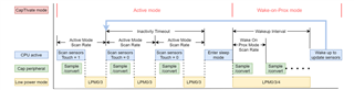
For the Keypad sensor design, I followed Ti's Design guide.

For testing the design I used the Ultra Low Power 4 button FR2633 code (modified to single button) provided by Ti in the Captivate Design Centre.

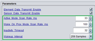
Touch works very well with the default parameters provided in the code, and I am trying to optimise the power consumption.

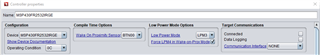
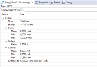
I am using the Captivate FR2633 energy trace to check the power consumption, and the best I achieve is 28 days (on a CR2032 battery setting).

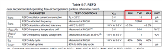
Referring to the Ti documentation, I was expecting 3 years (based on 6uA I-avg/Electrode), single button and Wake-on-proximity, external crystal.

There is probably something simple I am missing, and would appreciate some guidance/steps on how to resolve. Please let me know what further information you require.

Thanks in advance.

  • Hi Ty,

    From my side, I think the low power mode will have a great effect on this, which one do you used?

    And can you give me the link of document and I can also take a look of the instructions.

    B.R.

    Sal

  • Hello Sal, thank you for replying.

    Regarding 1st question, I have attached code. I am driving a TPS switch through P2.7 (labelled as LED in the code). LED on P1.0 is not activated. I have also added a delay to keep TPS on for a little while.

    void main(void)
    {
        //
        // Initialize the MCU
        // BSP_configureMCU() sets up the device IO and clocking
        // The global interrupt enable is set to allow peripherals
        // to wake the MCU.
        //
        WDTCTL = WDTPW | WDTHOLD;
        BSP_configureMCU();
        __bis_SR_register(GIE);
    
        //
        // Start the CapTIvate application
        //
        CAPT_appStart();
    
        //
        // Background Loop
        //
        while(1)
        {
            //
            // Run the captivate application handler.
            // Set LED1 while the app handler is running,
            // and set LED2 if proximity is detected
            // on any sensor.
            //
            LED1_TOGGLE;
            if(CAPT_appHandler() == true)
            {
                LED2_ON;
    
                // Add delay for 5 seconds
                __delay_cycles(100000000); // Assuming 1 MHz clock frequency
    
                LED2_OFF;
            }
            else
            {
                LED2_OFF;
            }
            LED1_OFF;
    
            //
            // This is a great place to add in any
            // background application code.
            //
            __no_operation();
    
            //
            // End of background loop iteration
            // Go to sleep if there is nothing left to do
            //
            CAPT_appSleep();
    
        } // End background loop
    } // End main()

    This is the CAPT_BSP.h code

    #ifndef CAPT_BSP_H_
    #define CAPT_BSP_H_
    
    #include <msp430.h>
    #include "driverlib.h"
    
    //*****************************************************************************
    //
    //! \def XT1_OSC_FREQ defines the frequency of the crystal oscillator on
    //! XIN/XOUT.
    //
    //*****************************************************************************
    #define XT1_OSC_FREQ                                                    (32768)
    #define XT1_OSC_TIMEOUT                                                 (65000)
    
    //*****************************************************************************
    //
    //! \def MCLK_FREQ defines the main clock frequency in Hz.
    //! \def SMCLK_FREQ defines the sub-main clock frequency in Hz.
    //! \def ACLK_FREQ defines the auxiliary clock frequency in Hz.
    //! \def FLLREF_FREQ defines the FLL reference clock frequency in Hz.
    //
    //*****************************************************************************
    #define MCLK_FREQ                                                    (16000000)
    #define SMCLK_FREQ                                                    (2000000)
    #define ACLK_FREQ                                                       (32768)
    #define FLLREF_FREQ                                                     (32768)
    
    //*****************************************************************************
    //
    //! \def FLL_RATIO defines ratio of MCLK to the FLL reference clock.
    //
    //*****************************************************************************
    #define FLL_RATIO                                     (MCLK_FREQ / FLLREF_FREQ)
    
    //*****************************************************************************
    //
    //! \def OSC_TIMEOUT defines the failure timeout for all oscillators.
    //
    //*****************************************************************************
    #define OSC_TIMEOUT                                                      (1000)
    
    //*****************************************************************************
    //
    //! \def LED1_POUT defines the port-out register LED1 is attached to.
    //! \def LED1_PDIR defines the port-direction register LED1 is attached to.
    //! \def LED1_PIN defines the port pin that LED1 is attached to.
    //! \def LED1_ON defines macro to turn on LED1.
    //! \def LED1_OFF defines a macro to turn off LED1.
    //! \def LED1_TOGGLE defines a macro to toggle LED1.
    //
    //*****************************************************************************
    #define LED1_POUT                                                       (P1OUT)
    #define LED1_PDIR                                                       (P1DIR)
    #define LED1_PIN                                                         (BIT0)
    #define LED1_ON                                         (LED1_POUT |= LED1_PIN)
    #define LED1_OFF                                       (LED1_POUT &= ~LED1_PIN)
    #define LED1_TOGGLE                                     (LED1_POUT ^= LED1_PIN)
    
    //*****************************************************************************
    //
    //! \def LED2_POUT defines the port-out register LED2 is attached to.
    //! \def LED2_PDIR defines the port-direction register LED2 is attached to.
    //! \def LED2_PIN defines the port pin that LED2 is attached to.
    //! \def LED2_ON defines macro to turn on LED2.
    //! \def LED2_OFF defines a macro to turn off LED2.
    //! \def LED2_TOGGLE defines a macro to toggle LED2.
    //
    //*****************************************************************************
    #define LED2_POUT                                                       (P2OUT)
    #define LED2_PDIR                                                       (P2DIR)
    #define LED2_PIN                                                         (BIT7)
    #define LED2_ON                                         (LED2_POUT |= LED2_PIN)
    #define LED2_OFF                                       (LED2_POUT &= ~LED2_PIN)
    #define LED2_TOGGLE                                     (LED2_POUT ^= LED2_PIN)
    
    //*****************************************************************************
    //
    //! This function is configures the MCU for operation.
    //! This involves setting up the digital IO muxes and configuring the clock
    //! system (CS).
    //
    //! \param none
    //! \return none
    //
    //*****************************************************************************
    extern void BSP_configureMCU(void);
    
    #endif /* CAPT_BSP_H_ */

    This is the CAPT_App.c code

    #include "captivate.h"
    
    //*****************************************************************************
    //
    //! \def Define CAPT_WOP_VLO_LPM4 in order to use the very low power oscillator
    //! (VLO) as the conversion timer in wake-on-proximity mode.  If this option
    //! is defined, LPM4 will be selected as the power mode, disabling ACLK and
    //! along with it XT1 or the REFO, whichever was sourcing ACLK previously,
    //! while the system is in WOP mode.  When WOP mode is exited and active
    //! mode is entered, ACLK will again be utilized to source the conversion timer
    //! and the application-selected low power mode (g_uiApp.ui8AppLPM) will be
    //! used until WOP mode is again entered.
    //!
    //! This option may be used to reduce the average current in wake-on-proximity
    //! mode for designs that do not have a crystal oscillator.
    //! If CAPT_WOP_VLO_LPM4 should be defined only if no CapTIvate COMM interface
    //! is selected (CAPT_INTERFACE == __CAPT_NO_INTERFACE__).
    //!
    //! Note that if this mode is selected and the VLO is used, the tolerance
    //! on the measured scan period will be poor.  For example, if 10 Hz (100ms)
    //! is the selected WOP scan rate, this value may vary by as much as +/- 5 Hz
    //! across temperature and voltage.  If this variance is too great for the
    //! application requirements, a 32kHz crystal or the REFO should be
    //! used instead.
    //
    //*****************************************************************************
    
    #ifdef CAPT_WOP_VLO_LPM4
    //*****************************************************************************
    //! \var g_ui8SavedAppLPM
    //! This variable is used as a context saving byte to recall the desired
    //! app low power mode in active operation.  When in wake on proximity mode,
    //! LPM4 will be used and the VLO will source the CapTIvate conversion
    //! timer directly.  This variable is only included in the build when
    //! CAPT_WOP_VLO_LPM4 is defined.
    //
    //*****************************************************************************
    static uint8_t g_ui8SavedAppLPM;
    #endif  // CAPT_WOP_VLO_LPM4
    
    void CAPT_appStart(void)
    {
        //
        // Initialize the user interface.
        // This function call enables the CapTIvate peripheral,
        // initializes and enables the capacitive touch IO.
        //
        MAP_CAPT_initUI(&g_uiApp);
    
        //
        // Load the EMC configuration, if this design has
        // noise immunity features enabled.  This function call
        // associates an EMC configuration with the EMC module.
        //
    #if (CAPT_CONDUCTED_NOISE_IMMUNITY_ENABLE==true)
        MAP_CAPT_loadEMCConfig(&g_EMCConfig);
    #endif  // CAPT_CONDUCTED_NOISE_IMMUNITY_ENABLE
    
        //
        // Calibrate the user interface.  This function establishes
        // coarse gain, fine gain, and offset tap tuning settings for
        // each element in the user interface.
        //
        MAP_CAPT_calibrateUI(&g_uiApp);
    
        //
        // Setup Captivate timer
        // This timer sets the g_bConvTimerFlag in the Captivate
        // library at the interval specified by CAPT_SCAN_INTERVAL.
        // This is used to trigger the app handler to update
        // the capacitive user interface.
        //
        MAP_CAPT_stopTimer();
        MAP_CAPT_clearTimer();
        MAP_CAPT_selectTimerSource(CAPT_TIMER_SRC_ACLK);
        MAP_CAPT_selectTimerSourceDivider(CAPT_TIMER_CLKDIV__1);
        MAP_CAPT_writeTimerCompRegister(CAPT_MS_TO_CYCLES(g_uiApp.ui16ActiveModeScanPeriod));
        MAP_CAPT_startTimer();
        MAP_CAPT_enableISR(CAPT_TIMER_INTERRUPT);
    
    #ifdef CAPT_WOP_VLO_LPM4
        g_ui8SavedAppLPM  = g_uiApp.ui8AppLPM;
    #endif  // CAPT_WOP_VLO_LPM4
    }
    
    bool CAPT_appHandler(void)
    {
    #if (CAPT_WAKEONPROX_ENABLE==true)
        static uint16_t g_ui16UISessionTimeoutCtr = 1;
    #endif  // CAPT_WAKEONPROX_ENABLE
        static bool bActivity = false;
    
        switch (g_uiApp.state)
        {
            case eUIActive:
                if (g_bConvTimerFlag == true)
                {
                    //
                    // Clear the conversion timer flag,
                    // and update the UI
                    //
                    g_bConvTimerFlag = false;
                    MAP_CAPT_updateUI(&g_uiApp);
                    bActivity = MAP_CAPT_getGlobalUIProximityStatus(&g_uiApp);
    
                    //
                    // If autonomous mode is enabled, check to
                    // see if autonomous mode should be entered.
                    //
    #if (CAPT_WAKEONPROX_ENABLE==true)
                    if (bActivity == true)
                    {
                        //
                        // If there is still a prox detection,
                        // reset the session timeout counter.
                        //
                        g_ui16UISessionTimeoutCtr = g_uiApp.ui16InactivityTimeout;
                    }
                    else if (--g_ui16UISessionTimeoutCtr == 0)
                    {
                        //
                        // If the session has timed out,
                        // enter autonomous mode
                        //
                        g_uiApp.state = eUIWakeOnProx;
                        bActivity = false;
    
                        //
                        // Set the timer period for wake on touch interval
                        //
                        MAP_CAPT_disableISR(CAPT_TIMER_INTERRUPT);
                        MAP_CAPT_stopTimer();
                        MAP_CAPT_clearTimer();
    #ifndef CAPT_WOP_VLO_LPM4
                        MAP_CAPT_writeTimerCompRegister(CAPT_MS_TO_CYCLES(g_uiApp.ui16WakeOnProxModeScanPeriod));
    #else
                        MAP_CAPT_selectTimerSource(CAPT_TIMER_SRC_VLOCLK);
                        MAP_CAPT_writeTimerCompRegister(CAPT_MS_TO_CYCLES_VLO(g_uiApp.ui16WakeOnProxModeScanPeriod));
                        g_uiApp.ui8AppLPM = LPM4_bits;
    #endif  // CAPT_WOP_VLO_LPM4
                        MAP_CAPT_startTimer();
                        g_bConvTimerFlag = false;
                        MAP_CAPT_startWakeOnProxMode(
                                &CAPT_WAKEONPROX_SENSOR,
                                0,
                                g_uiApp.ui8WakeupInterval
                                );
                    }
    #endif  // CAPT_WAKEONPROX_ENABLE
                }
                break;
    
            case eUIWakeOnProx:
    #if (CAPT_WAKEONPROX_ENABLE==true)
                if (g_bDetectionFlag || g_bConvCounterFlag || g_bMaxCountErrorFlag)
                {
                    //
                    // If a detection, conversion counter, or max count error flag was set,
                    // stop autonomous mode and reload an active session
                    //
                    MAP_CAPT_stopWakeOnProxMode(&CAPT_WAKEONPROX_SENSOR, 0);
                    g_bDetectionFlag = false;
                    g_bConvCounterFlag = false;
                    g_bMaxCountErrorFlag = false;
                    g_uiApp.state = eUIActive;
                    g_ui16UISessionTimeoutCtr = g_uiApp.ui16InactivityTimeout;
    
                    //
                    // Set the timer period for normal scan interval
                    //
                    MAP_CAPT_disableISR(CAPT_TIMER_INTERRUPT);
                    MAP_CAPT_stopTimer();
                    MAP_CAPT_clearTimer();
    #ifdef CAPT_WOP_VLO_LPM4
                    MAP_CAPT_selectTimerSource(CAPT_TIMER_SRC_ACLK);
                    g_uiApp.ui8AppLPM = g_ui8SavedAppLPM;
    #endif  // CAPT_WOP_VLO_LPM4
                    MAP_CAPT_writeTimerCompRegister(CAPT_MS_TO_CYCLES(g_uiApp.ui16ActiveModeScanPeriod));
    
                    MAP_CAPT_startTimer();
                    MAP_CAPT_clearIFG(CAPT_TIMER_INTERRUPT);
                    MAP_CAPT_enableISR(CAPT_TIMER_INTERRUPT);
                }
    #endif  // CAPT_WAKEONPROX_ENABLE
                break;
        }
    
    #if ((CAPT_INTERFACE==__CAPT_UART_INTERFACE__) ||\
        (CAPT_INTERFACE==__CAPT_BULKI2C_INTERFACE__) ||\
        (CAPT_INTERFACE==__CAPT_REGISTERI2C_INTERFACE__))
        //
        // If communications are enabled, check for any incoming packets.
        //
        CAPT_checkForInboundPacket();
    
        //
        // Check to see if the packet requested a re-calibration.
        // If wake-on-prox is enabled and the current application state
        // is wake-on-prox, disable the wake-on-prox feature during the calibration
        // and re-enable it after the calibration.
        //
        if (CAPT_checkForRecalibrationRequest() == true)
        {
    #if (CAPT_WAKEONPROX_ENABLE==true)
            if (g_uiApp.state == eUIWakeOnProx)
            {
                MAP_CAPT_stopWakeOnProxMode(
                        &CAPT_WAKEONPROX_SENSOR,
                        0
                        );
                MAP_CAPT_calibrateUI(&g_uiApp);
                MAP_CAPT_startWakeOnProxMode(
                        &CAPT_WAKEONPROX_SENSOR,
                        0,
                        g_uiApp.ui8WakeupInterval
                        );
            }
            else
            {
                MAP_CAPT_calibrateUI(&g_uiApp);
            }
    #else
            MAP_CAPT_calibrateUI(&g_uiApp);
    #endif  // CAPT_WAKEONPROX_ENABLE
        }
    #endif  // CAPT_INTERFACE
    
        return bActivity;
    }
    
    void CAPT_appSleep(void)
    {
        //
        // If no captivate flags are set, enter the application's low power
        // mode.  Otherwise, re-enter the background loop immediately.
        //
        __bic_SR_register(GIE);
        if (!(g_bConvTimerFlag ||g_bDetectionFlag || g_bConvCounterFlag || g_bMaxCountErrorFlag))
        {
            __bis_SR_register(g_uiApp.ui8AppLPM | GIE);
        }
        else
        {
            __bis_SR_register(GIE);
        }
    }


    In my code (generated by the captivate design centre), I have LPM3, with force LPM on prox mode as below;

    Regarding link of document, please refer to https://software-dl.ti.com/msp430/msp430_public_sw/mcu/msp430/CapTIvate_Design_Center/latest/exports/docs/users_guide/html/CapTIvate_Technology_Guide_html/markdown/ch_design_guide.html#ultra-low-power (this explains what power consumption to expect in my setup).

    Please let me know which other information you require.

    Thank you again.

  • Hi Ty,

    Thanks for the details, I will forward to the CapTivate expert and get his comments.

    B.R.

    Sal

  • Can you tell me your average current now?

    Can you check whether your added code caused the additional current.

  • Hi Eason, thank you for replying. My lifetime of battery is at 28 days (this is without activating LED or TPS)

  • Thank you Sal. Awaiting your response.

  • Hi Ty,

    Thanks for your informarion, Eason is the expert on CaTivate. Let's wait for his advice.

    B.R.

    Sal

  • Can you tell me the averaging current? Then I can use this to check what the power level now.

    Can you send me your code? I can help you look into it to see part happens.

  • Hello Eason, I hope you are well. Please see attached link to my workspace. I have also attached the screenshots from energy trace.

      https://drive.google.com/file/d/1aEKprsoE-rpIjIuJyfsOc9BOf7p3Zkpu/view?usp=drive_web

    Please let me know if you require any further information.

  • Can you just upload the code to e2e? Sorry, we can't get access to google share

  • Hi Eason, thank you for the reply. I pasted the code earlier in the thread. Is this sufficient, or do you need anything more specific from the workspace? 

    I have attached code.

    This is the CAPT_App.c code

    This is the CAPT_BSP.h code
  • Can you post the whole project. Then I can do the debug.

    You can also change these parameters to see if the current can meet your requirement. Like make the inactivity timeout to be smaller. Wakeup interval to be longer. 

  • Hi Eason, I hope you are well.

    Please see attached as requested.

    workspace_v13 (1).zip

  • Have you try my suggestion to make the optimizaiton?As the lowest current meet the LPM3 and the LPM setting is right, I think there is little you can do to optimize the low power current. The poblem will be how to adjust the active current. Please try to adjust according to my suggestions. 

  • Hi Eason, thank you for the reply. I havent tried your suggestion. I will check today and feedback tomorrow. My original query was why I couldnt achieve the ffg using the 4 button ultra low power code and instruction from ti;

    3 years (based on 6uA I-avg/Electrode), single button and Wake-on-proximity, external crystal

    My target is 1 year, but currently, I am only achieving 1 month (at best).

  • Because it only have 1 button, but you have 4 buttons. at least 4x current. Besides, it use external crystal, can you check your hardware setting? It will add a little more current. 

    However as you enter LPM4 mode, using VLO clock, I think it will not affect too much.

  • Hi Eason, I hope you are well. I have managed to find the issue with my custom board. Another component was not being initialised properly and drawing the current. I am now getting expected LPM values. Thank you for your support.

**Attention** This is a public forum