This thread has been locked.

If you have a related question, please click the "Ask a related question" button in the top right corner. The newly created question will be automatically linked to this question.

EVM430-FR6047: EVM430-FR6047

Part Number: EVM430-FR6047
Other Parts Discussed in Thread: MSP430FR6041, MSP430WARE, MSP430FR6043, MSP430FR5043, MSP430FR5041

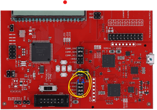
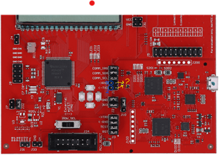
Hello Everyone, I am using EVM430FR6047 evaluation board in my project and I am trying to establish a UART communication with another UART compatible board. In the past I usually worked with Arduino boards which were easier to do UART communication with another one, although I checked the datasheets and user guide I was not able to understand how to do.

TXD and RXD has 2 pin teeths How should I do my wirings on RXD - TXD ? can someone help me please. Thank you 

  • Hi Umut,

    The hardware/wiring should be as simple as any other device, connect the TX of one board to the RX of the other, for both pins on each board. You should also be sure to check that you are using the correct UART pins.

    Are you using one of our example codes to utilize the UART peripheral? We have example codes available in our SDK. Please see the folder: msp430ware_3_80_14_01\examples\devices\MSP430FR5xx_6xx\MSP430FR6043_MSP430FR6041_MSP430FR5043_MSP430FR5041_Code_Examples\C

    In here you will find many UART examples to help you write your code.

  • Hello Dylan,

    Thanks for your answer. I tried it as same as the other hardwares already however it didn`t work maybe I made something wrong. What confuses me here is for example in arduino boards there is RX TX as 1 pin socket. However here there is 2 sockets in which one i should put? or should i to both of them ?


  • Hi Umut,

    I see what you mean now. That header is used to connect the MSP430FR6043 to the eZ-FET debugging tool. So in the image you've pasted, the top left pin is the UART TX from the MSP430FR6043, and the top right pin is the UART RX for the eZ-FET debugger. Similarly, the left pin in the 2nd row is the MSP430's UART RX, and the right pin in the second row is the eZ-FET's UART TX. These pins should be connected using jumpers, as shown in the image, when you want to connect to the eZ-FET with UART. 

    If you want to use them as a regular UART peripheral connected to the MSP430FR6043, then you can connect the pins on the left side of the header as labeled on the device.

    You may want to take a look at the EVM430-FR6043 hardware guide for more information on the device hardware.

  • Hi Dylan, 

    I want to use them as a regular UART peripheral. I want to establish a communication between EVM430FR6047 and a motor driver board using UART. What do you mean by Header exactly ?  as far as I understood from your message I should connect my wires like this to the pins I wrote 1 & 2 with blue colour ? if so then what about the pins next to them which I made an arrow and question mark with yellow colour? what are they for? is it GND ?

  • A header is just a set of pins. So in the first image you posted, if I say "header J3", I am talking about the set of pins that are all next to each other and labeled J3. These would be the 8 pins that you circled.

    In your first image, you circled header J3, in this most recent image, you circled header J1. Was this a mistake, or do you want to use J1 now?

    In either case, the pins on the left side are the ones that connect to the MSP430. The pins on the right side connect to the debugger (or HID bridge for J1). You can connect your UART device to the left side pins, and leave the pins on the right side disconnected.

  • Now I got my answer. Thank you so much :):) 

**Attention** This is a public forum