This thread has been locked.

If you have a related question, please click the "Ask a related question" button in the top right corner. The newly created question will be automatically linked to this question.

MSP430FR50431: Problem with configuring routines

Part Number: MSP430FR50431
Other Parts Discussed in Thread: MSP430FR6043,

Hi,

I am trying to alter the FR6043_USSSWLib_template_example to work with my setup.

Most of the other parts work for me, but I have trouble getting this function to work.

code = USS_configureUltrasonicMeasurement(&gUssSWConfig);

The compiler does not throw an error but when I execute my code, it gets stuck on that routine.

Do you have any suggestions on how I could approach this problem?

Best regards,

Lukas

  • Hi Lukas,

    What steps have you taken to change the FR6043 code to work on the FR5043?

    Additionally, when you say that it gets stuck, you are saying the project hangs there when you are debugging? If that is the case, could you step into the function and indicate more specifically where it hangs? I have not observed this behavior before personally.

    I assume this also means that you never get any data out of the UART interface? Please verify this.

    You also may want to keep watch of this thread, where another customer seems to be having issues using the template example on the FR5043. It seems that my colleague is going to do some testing on it soon to verify. 

  • Thank you for your response.

    I am trying to use the UART example and the msp430fr6043_euscib0_i2c_11.c together to get the same values that normally are transmitted via uart to be transmitted via i2c. For that purpose I am trying to merge the two examples together.

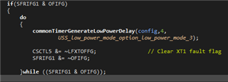
    I have tried to debug and found out that the code is trapped here:

    in the "ussSwLibCommonTimer.c". It can never leave this while loop apparently. Do you have any suggestions where this might come from?

    The only thing I changed was to siwtch the device to the msp430fr50431 in Code Composer Studio which worked for both example codes but does not anymore as I am trying to merge the code together.

  • To be even more precise, in the commonTimerGenerateLowPowerDelay(...) in my first picture, it is stuck at this while loop already:

  • It looks like that loop is used to take care of an oscillator fault. Normally what is supposed to happen is the loop delays for 800ms then clears the flag. However it looks like your device enters LPM3 and then never enters active mode again. Is there any reason that you would expect an oscillator fault, such as damage to the device or changes to the hardware?

    So you only changed the device version in CCS, and nothing else? You said you are trying to use the I2C_11 example together with the demo so I am unsure if you have started making these changes yet. It seems that many customers have issues waking up from LPMs when adding interrupts (specifically I2C interrupts) to the demo project. If there have been other changes, did this project work on your device before making them?

    Additionally, were you able to look at the files that my colleague provided regarding changing the USS projects for use with the FR5043?

  • The oscillator seems to work fine when observed with an oscilloscope. I am using a 16MHz oscillator on the USSXTOUT/TIN pins. Changes I made were:

    - use the pin configurations of msp430fr6043_cs_02.c to change the clock to 16 MHz.

    - replaced the linker file and USS_Lib_HAL.h with the files provided by your colleague

    - changed the device to msp4030fr50431

    - took the pin configuration from ...euscib0_i2c_11.c and the ISR with the TxData example

    I can read the test data over i2c. Once I uncomment those lines:

    code = USS_commonTriggerSingleCapture(&gUssSWConfig,1,2000);
    code = USS_startUltrasonicMeasurement(&gUssSWConfig,USS_capture_power_mode_active);
    code = USS_startLowPowerUltrasonicCapture(&gUssSWConfig);
    code = USS_runAlgorithms(&gUssSWConfig,&algResults);

    I can't read anything over i2c as the interrupt does not seem to work anymore.

  • Thanks for checking this.

    Looking at our datasheet section 8.13.14.3 USSXTAL, the acceptable frequency range for USSXTAL is 4MHz to 8MHz.

    Additionally, to be clear, msp430fr6043_cs_02 changes the DCO to 16MHz, then outputs SMCLK to pin 3.4. This is not changing the pin configuration to allow a 16MHz crystal. I am not 100% sure if that was your goal with this but be aware of that note. 

    This does make sense to me that your I2C could still function properly here, but the USS peripheral is experiencing issues. Could you try swapping your crystal for an 8MHz or 4MHz crystal to see if this allows your device to behave properly? It is possible that there are other issues but this should help.

  • Thank you for your help so far. I changed the crystal to 8MHz and at least the setup routines do now work.

    Now I have the issue that I get the error: "USS_message_code_algorithm_error_no_signal_detected_ups_dns_channel" when reading the "code" variable via JTAG during testing. Do you know what the problem here might be? When I use the MULTI_TONE configuration, I can see two sets of pulses on the oscilloscope when probing CH0_OUT. Does the signal get registered by ch0_in and the second set of pulses already is the reflection of the signal? Or are both of the puls sets coming from ch0_out and I should measure them in ch1_in in order to avoid the error?

  • I am glad that we are making progress Lukas. 

    This error indicates that the device has a poor connection, or no connection, with the transducers. Can you verify that the transducers are connected correctly?

    If so, you may want to try switching to the USS_Demo codes, as this will allow you to view the ADC capture in the GUI. This will help you make sure that the issue is actually that the transducers are not connected properly. If the ADC capture looks good, then you know there is some other issue. If the ADC capture looks bad, then this confirms that the transducers are making a poor connection.

    Without seeing the timing on these pulses, it would be hard to say whether the second set of pulses is the reflection, or the second ultrasonic signal (for UPS  vs DNS signal). When probing the CH0 and CH1 in and out pins, you will likely be able to see the UPS and DNS signals, as well as some of their reflections. The UPS and DNS signal should have very similar large amplitudes compared to reflecting signals.

  • I have probed the two channels but the signal does not look great on the ch1 in (yellow) as it seems..

    I am currently driving the transducers directly from the pins without additional amplification. Might that be a problem?

  • That is interesting. I assume that ch.2/green is connected to CH.0 of the MSP's analog front end? So those waveforms at 0s and ~4ms are the CH.2 excitation signals? Please confirm this.

    If the above is true, then I would think that you do not need additional amplification. Is it possible that the AFE channel is not properly connected to the transducers, such as poor wiring or something? Or do you think that some of the code changes you made are affecting the excitation of that channel?

    If it is possible for you to program the device with the demo code instead of the template example, this is very helpful as it allows you to see the waveform that the MSP gets, which can be helpful. It also allows for easier calibration, so you can eliminate calibration errors. Then you can move your calibration data over from the demo code to the template example and start from a known base point.

    Bottom line is, yes it looks like the signal connected to the ch1 transducer is bad, so first I'd encourage you to check your hardware to ensure that a good excitation signal is enabled, then check over your software to make sure you haven't accidentally changed something with that pin, or with the sequence to excite it.

  • My apologies for the late response.

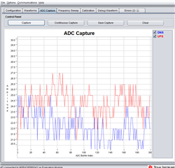
    I am now trying to get my transducer setup running with the eval board first and then come back to my own code with the implemented chip. I am currently getting quite bad results there as well but that might just appear because of poor parameter settings. If you have some tips on how to improve this I would appreciate it. After I get this running I am going to try implementing it on our system. Right now the adc apture looks like this..

    Thanks again for your help so far.

  • Hi Lukas, no worries,

    Yes as you said, the ADC capture does not look good. It is possible that this is caused by the settings, but it is also possible that this is due to your hardware. To start with, you should probably go to the USS academy for tips on getting started setting your parameters correctly.

    Some of this may be repetitive for you but it does walk you through the initial configuration of the parameters, and through the frequency sweep test. These two should get you to a good starting point. Sometimes, waveforms like what you are seeing in your screenshot can be caused by an incorrect excitation frequency (which the frequency sweep will help you with), or if your ADC capture is looking at the wrong portion of the waveform, which could be helped by increasing the capture duration, changing the gap between pulse start and ADC capture, and other settings.

    There are certainly a few settings that could lead to this issue. I would also encourage you to verify that your hardware is connected correctly, particularly the transducers to the pins on the board. If your transducers are bad, if the wire connecting them is bad, or if their connection to the pins are bad, it could result in a small, ineffective waveform, like what you see in your ADC capture. Based on the appearance of your oscilloscope capture above, I would think that one of your transducers is not connected well. You may want to see the EVM430FR6043 hardware users guide for tips with the device hardware and with the USS ecosystem.

  • Hi, new day new questions.. Slight smile

    I managed to get the adc capture working more or less after I flashed the eval board again. I then exported the header file in the USS to the  USSSWLib_template_example in code composer studio to run on our system. I now have the trouble of some USS_message_error occuring.

    If I do not connect any transducers, I get the message 122 (.._valid_results) ??

    but when I connect the transducers I get the message 127 (.._no_signal_detected_...)

    Do you have any idea why this might be the case?

  • Could you please post an image of your working ADC capture? I'm not sure that it is the root of the issue but it would be helpful to see.

    Looking at the template example code, it looks like USS_message_code_valid_results is assigned to the code variable at the end of the USS_calibrateVFRFlowTemperature() function, and the end of the USS_calibrateVFRFlow() function. So it makes sense to me that this code could be generated even when the transducers are not connected. Not that I think this is good necessarily, but it does make sense. 

    Searching through the code, I do not actually see where error code 127 is generated or assigned to the code variable. This makes me think that the USS algorithm determines this and assigns it to the code variable. While we can't look into the code for this further, I do think that this error message is correctly indicating that the downstream signal from one of your transducers is not detected. This also makes sense considering your oscilloscope capture posted earlier, where only one channel could be seen generating the correct waveform. 

    Have you had the opportunity to try swapping out your transducers? I assume you have already verified the wiring connecting them.

  • Hi Dylan,

    I turns out my transducers are connected in a different way than on the eval board which might explain why it works on the eval boarad but not on my setup.

    I assumed that I can send pulses from CH0_OUT to be recieved on CH1_IN and vice versa. However as I looked on the schematic of the dev board again it seems to me that only CH0 is used for the whole ciruit and the UPS and DNS are observed by swapping the direction of transducers with analog signal switches. Can you confirm that I got that right?

    And if, is there a possiblility to start the timer as soon as CH0_OUT has sent the pulses and stop it when CH1_IN regognized them? Is there a parameter I can choose the used channel from? Or won't it be possible to do so because of the nature of the used interrupts e.g. ?

  • Or to be more precise after reading the documents once again: Which parameter in the USS design center or the example code changes the properties in order to use ch0_out to ch0_in for upstream and ch1_out to ch1_in for the downstream for example?

  • Hi Lukas, 

    You are correct that in the FR6043 design files, we use CH0 + mux to perform the reading. 

    The defines that you are looking for in order to change the order of the pulse sequence is USS_SEQUENCE_SELECTION, found in USS_userConfig.h.

    In the code you will see that you can choose a few different sequences. Some short explanation of the meaning of each of these can be found in this e2e post. You'll have to do some testing to find which excitation sequence is necessary for your hardware. 

**Attention** This is a public forum