This thread has been locked.

If you have a related question, please click the "Ask a related question" button in the top right corner. The newly created question will be automatically linked to this question.

MSP430FR6043: Output PWM

Part Number: MSP430FR6043

I'm trying to output a PWM signal corresponding to ToF. Testing it with 50% duty cycle right now to verify I can get the signal on the pin I expect.

Within system_pre_int.c I added the code below.

/* Insert your low-level initializations here */

/* Disable Watchdog timer to prevent reset during */
/* int32_t variable initialization sequences. */
// Stop WDT
WDTCTL = WDTPW + WDTHOLD;

P1DIR |= BIT2;
P1SEL0 |= BIT2;
TA0CCR0 = 1000;
TA0CCTL1 = OUTMOD_7;
TA0CCR1 = 500;
TA0CTL = TASSEL_2 + MC_1;

The voltage on the pin which maps to this changed from 0V to 3.3V once I loaded this code on. Wondering what I am doing wrong and not getting a 50% duty cycle.

  • Per data sheet (SLASEF5B) Table 9-26, you've set P1.2 for UCA1TXD (PSEL=01), which would normally put out a high (1) level. Another function for P1.2 (PSEL=10) is TA1.0, which is (a) timer TA1, not TA0 and (b) not really suitable for ("real") PWM.

    PWM is available on other pins. Is your goal to use a particular pin, or a particular timer?

  • Hi Bruce - I appreciate the response. It's my first time trying to program something like this so a bit lost. My end goal is to encode the time of flight signal from the ultrasonic sensor into PWM. Starting out by verifying I can output 50% from the board. Which pin would you recommend for this?

  • What pins do you have available? I ask since (e.g.) on the EVM it seems like most of the pins are already used.

    P1.3 can output PWM from TA1 as TA1.1 [Ref Table 9-26 again]. For that you might use:

    P1DIR |= BIT3;            // P1.3 as TA1.1 per
    P1SEL1 |= BIT3;           //  SLASEF5B Table 9-26
    TA1CCR0 = 1000-1;         // 1ms period (SMCLK=1MHz)
    TA1CCTL1 = OUTMOD_7;      // On at CCR0, Off at CCR1
    TA1CCR1 = 500;            // 0.5ms on for 50% duty
    TA1CTL = TASSEL_2 + MC_1; // SMCLK, Up 

    [Edit: Forgot the -1 on CCR0.]

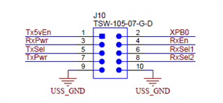
  • I'll work on that and make sure I'm loading the code onto the board in the right way. I haven't had any luck yet. Just reads 0V. J10 on the board is listed as GPIOs. TxSel J10-5 connects to P2.3 and TA0.0. I will keep trying to see if I can get anything to read from these.


  • Your code configures the output mode for TA0.1 to PWM. So that is the pin you should use with that code. Searching through the data sheet, that appears at P6.7

  • You set me on the right path - I found an example using Timer B from Code Composer Studio. It creates two PWM on P3.1 and P3.7. I modified it to use only P3.1 which I can access on J13-1 on the EVM board. The problem I am having now is updating TB0CCR1.

    Here is the code - I merged a solution from another thread with the PWM example to test it out. Right now the duty cycle is static with what I initially set.

    #include <msp430.h>
    
    int main(void)
    {
        static int counter   = 110;                      // Cycle counter
        static int  direction = 1;                      // 1: up, 0: down
    
        WDTCTL = WDTPW | WDTHOLD;               // Stop WDT
    
        // Configure GPIO
        P3DIR |= BIT1                  // Select output
        P3SEL0 &= ~BIT1               // Select functions
        P3SEL1 |= BIT1
    
        // Disable the GPIO power-on default high-impedance mode to activate
        // previously configured port settings
        PM5CTL0 &= ~LOCKLPM5;
    
        TB0CCR0 = 1000-1;                       // PWM Period
        TB0CCTL1 = OUTMOD_7;                    // CCR1 reset/set
        TB0CCR1 = 500;                          // CCR1 PWM duty cycle
        TB0CTL = TBSSEL__SMCLK | MC__UP | TBCLR | TBIE;// SMCLK, up mode, clear TBR
    
        __bis_SR_register(GIE);
        __bis_SR_register(LPM0_bits);           // Enter LPM0
        //__no_operation();                       // For debugger
        while( 1 )                                         // Endless loop
        {
    
    
        // Timer0 A1 interrupt service routine
        #pragma vector = TIMER0_A1_VECTOR
        __interrupt void Timer0_A1_ISR( void );


        TB0CTL &= ~TBIFG;                                // Clear interrupt flag
    
            if( ++counter >= 50000 )                            // 5s
            {
              if( direction )                                   // Direction is up
              {
                  TB0CCR1 += 10;                                  // Add 5% to existing value
    
                if( TB0CCR1 == 900 )                            // Reached 50% duty cycle
                {
                  direction = 0;                                // Next time down
                }
              }
              else                                              // Direction is down
              {
                  TB0CCR1 -= 100;                                  // Subtract 5% from existing value
    
                if( TB0CCR1 == 100 )                             // Reached 5% duty cycle
                {
                  direction = 1;                                // Next time up
                }
              }
    
              counter = 0;                                      // Reset counter
            }
        }
    }

  • It looks mostly right, except that:

    1) You seem to have coded the ISR in the middle of main()'s while(1) loop. As a practical matter, this would (sort of accidentally) do something, except that

    2) Before the while(1) loop you put the CPU into LPM0, with no mechanism to wake up.

    The simplest fix would be to move the lines starting with "#pragma" down to the bottom of the file, adjusting closing braces ("}") as needed, so Timer0_A1_ISR() is a separate function, and the while(1) in main() is empty (which is fine since you'll never get there due to the LPM0).

  • Trying to understand how to eventually implement this in the USS application. There's a file called system_pre_init.c where I setup the timer to output the PWM, then in main.c there's a while(1) loop which performs the ultrasonic capture. I want to extract the results from that capture and send it out via PWM each time that loop runs. Do I have to disable LPM to be able to change PWM duty cycle?

    Would I do something like

    while(1)

    {

    // USS Capture happens

    //Wake up from LPM

    //Interrupt

    // Change PWM duty cycle

    // Return to LPM

    }

  • I'm not sure what I have wrong here. I've been reading examples and trying to understand how to use the Timer B interrupt. Here's what I have. I have a scope hooked up and trying to see I can change duty cycle, but it stays fixed with the value I initialize in main. Thanks in advance for your help.

    #include <msp430.h>
    static int IncDec_PWM   = 1;
    
    int main(void)
    {
    
        WDTCTL = WDTPW | WDTHOLD;               // Stop WDT
    
        // Configure GPIO
        P3DIR |= BIT1;                  // Select output
        P3SEL0 &= ~BIT1 ;              // Select functions
        P3SEL1 |= BIT1;
    
        // Disable the GPIO power-on default high-impedance mode to activate
        // previously configured port settings
        PM5CTL0 &= ~LOCKLPM5;
    
        TB0CCR0 = 1000-1;                       // PWM Period
        TB0CCTL1 = OUTMOD_7;                    // CCR1 reset/set
        TB0CCR1 = 10;                          // CCR1 PWM duty cycle
        TB0CTL = TBSSEL__SMCLK | MC__UP | TBCLR | TBIE;// SMCLK, up mode, clear TBR
    
        __bis_SR_register(LPM0_bits + GIE);
    
        while(1){}
    }
    
    #pragma vector = TIMER0_B1_VECTOR
    __interrupt void Timer0_B1_ISR( void ){
    
        TA0CCR1 += IncDec_PWM;
        if( TA0CCR1 > 990 || TA0CCR1 < 10 )
               IncDec_PWM = -IncDec_PWM;
    }

  • Figured it out - I copied a Timer A example. If I change the TA to TB in the Timer0_B1_ISR it changes the duty cycle for me.

  • How to you recommend to trigger this change when I get a time of flight signal from the ultrasonic algorithm in main.c? Would I create a function like Timer0_B1_ISR and call it?

  • I don't know what your target main() loop looks like, but I suppose it's constructed with an overall dynamic in mind. You shouldn't change this; in particular, don't e.g. add LPM or enable/disable interrupts.

    I imagine your contribution to the loop will be two lines of code: (a) compute an  appropriate duty cycle based on the most recent capture (b) store that value into TB0CCR1. You don't need an ISR (there's nothing for it to do), so don't set TBIE.

    Other[1]: Since you're using TimerB, I suggest you set CLLD=2 to avoid glitches. This might look something like:

    > TB0CCTL1 = OUTMOD_7|CLLD_2;                    // CCR1 reset/set, update shadow at TB0R==0.

    Other [2]: So far the code you're putting into _sys_pre_init is fine. Keep in mind, though, that this function is called before C initialization, so don't add code which relies on initialized variables (including =0).

  • Other[1]: Since you're using TimerB, I suggest you set CLLD=2 to avoid glitches. This might look something like:

    Just a passer-by; this made me waste a couple days on a previous project. Synchronized CCR loading doesn't actually work on the FR6043. See the Errata, TB25.

  • No, I didn't notice this. Thanks for pointing it out. Seems like it applies to other FR5/FR6 devices as well.

  • Thanks Bruce - I appreciate the help! It appears to be working now. I had to insert the duty cycle calculation in a specific spot in the while loop to get it to work. Scaling it to be between 100 to 900. 

       while(1)
        {
    
            code = USS_startLowPowerUltrasonicCapture(&gUssSWConfig);
            checkCode(code, USS_message_code_no_error);
    
            code = USS_runAlgorithms(&gUssSWConfig,&algResults);
            checkCode(code, USS_message_code_valid_results);
    
            TB0CCR1 = (int)(algResults.totalTOF_UPS * 50571428.57 - 10900);
    #if (APPLICATION_ENABLE_CHANNEL_SWAP == true)

**Attention** This is a public forum