This thread has been locked.

If you have a related question, please click the "Ask a related question" button in the top right corner. The newly created question will be automatically linked to this question.

MSP430FR5969: Delay in switching PWM frequency

Part Number: MSP430FR5969

Hello, 

I am trying to run two timers: TimerA and TimerB for pwm generation simultaneously.

Timer A : clock source is TACLK using external crystal of 16MHz (provided from pin 3.4 of another msp430fr5969 having populated Y1 with 16 MHz crystal)
Timer B: clock source is SMCLK which is mapped to MCLK at 16 MHZ (DCO source)

My final aim is to generate 2FSK signal at high baudrates for that I am using timer A as my baudrate source and Timer B to generate 2 frequencies of FSK

Relevant code snippets: 

void set_cpu_freq() {

FRCTL0 = FRCTLPW | NWAITS_1;
CSCTL0_H = CSKEY >> 8; // Unlock CS registers
CSCTL1 = DCORSEL | DCOFSEL_4; // Set DCO to 8MHz
CSCTL2 = SELA__VLOCLK | SELS__DCOCLK | SELM__DCOCLK;
CSCTL3 = DIVA__1 | DIVS__1 | DIVM__1; // Set all dividers to 1

}

int main(void) {


WDTCTL = WDTPW | WDTHOLD; // Stop watchdog timer


P1OUT &= ~BIT3; // Clear P1.0 output latch for a defined power-on state
P1DIR |= BIT3; // Set P1.0 to output direction

P1DIR &= ~BIT2;

PM5CTL0 &= ~LOCKLPM5; // Disable the GPIO power-on default high-impedance mode
// to activate previously configured port settings

set_cpu_freq();

while (1) {
//message generation code: generates an array with binary information

__enable_interrupt();
TA0CTL = TASSEL__TACLK | MC_1 | TACLR; // SMCLK, Up mode, no divider
TA0CCR0 = (16000000/10000) - 1; // Set period based on SMCLK frequency
TA0CCTL0 = CCIE; // Enable interrupts
TA0CCTL1 = OUTMOD_7;

TB0CTL = TBSSEL__SMCLK | TBCLR | MC_1 ; // SMCLK, up mode, /8 divider
TB0CCTL1 = OUTMOD_7;
TB0CCTL0 = CCIE; // Enable CCR0 interrupt

delay_ms(100);

}


}

#pragma vector=TIMER0_B0_VECTOR
__interrupt void Timer0_B0 (void)
{
    P1OUT ^= BIT3; // Generates the FSK frequency 
}

__attribute__((interrupt(TIMER0_A0_VECTOR))) //controls the baud rate of the FSK signal
void timer_a0_isr(void) {

if (tx_counter < TXLEN){

    if (arr[tx_counter] == 0){
        TB0CCR0 = (CPU_FREQ/(2*300000)) -1;
    }
    else if(arr[tx_counter] == 1){
        TB0CCR0 = (CPU_FREQ/(2*400000)) -1;
    }
    tx_counter++;
}
else{
    tx_counter = 0;
    disable_signal();
    msp430_timer_stop();
}

}

Problem: 

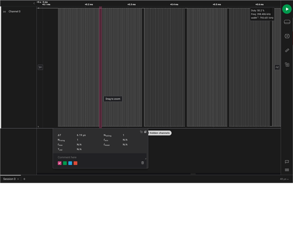
As depicted in the below image, I observed delays of about 6-7 microseconds between frequency switches, initially I was using SMCLK for both of the Timers A and B, observing the same issue, I assumed this must be an issue originating from the fact that both the timers using same source i.e SMCLK, I switched to the current setup of using TACLK for Timer A annd SMCLK for Timer B but the same issue persists, resulting in limitations of baudrate as the 6-7 microsecond gap becomes much more significant as I increase the baudrate eg 30kbps. My aim is to have atleast 100Kbps of baudrate.


Anticipating some suggestions from the community to mitigate this issue.

Regards!

  • 1) I'm not quite sure how TASSEL_TACLK is working at all, since I don't see a P1SEL1 setting for TA0CLK (P1.2). I recommend you use SMCLK for both timers.

    2)  Are you required to use P1.3 for the FSK clock? It looks like P1.4 can output TB0.1, so setting TB0CCTL1 to OUTMOD_4 (toggle) would give you the signal you have now, but with no latency. I suspect those gaps in your scope trace come from this latency (while the TA0CCR0 ISR is running).

    3)  Your CCR0 update has a very tight deadline (20 or 26 timer ticks). You may want to consider using DMA instead of software to update TB0CCR0. [Ref data sheet (SLAS704G) Table 6-12]

    I think (2) is what you're looking at now, and (3) is what you'll encounter next.

    [Edit: I just noticed P1.3 can provide TA1.2 [Ref data sheet Table 6-50], so if you can't switch pins ((2) above) that's an option.]

  • 1) I'm not quite sure how TASSEL_TACLK is working at all, since I don't see a P1SEL1 setting for TA0CLK (P1.2).
    Mistake on my part. I removed the line
    P1SEL1 |= (BIT2); // Set P1.2 SEL as TA0CLK
    while writing the query. TACLK works because removing the jumper from P1.2 results in no output from Timer A.

    2) I switched to P1.4 as suggested for FSK output using the following addition and changes in the code: 
    int main(void){
        P1SEL0 |= BIT4; //sets pin 1.4 to special function output
        P1DIR |= BIT4; //sets pin 1.4 for output for channel 1 PWM
    }

    TimerB config: 

    TB0CTL = TBSSEL__SMCLK | TBCLR | MC_1 ; // SMCLK, up mode, /8 divider
    TB0CCTL1 = OUTMOD_4;
    TB0CCTL0 = CCIE; // Enable CCR0 interrupt

    Removed the ISR for TimerB

    The output frequency is stuck on a single frequency of 500KHz, it should change corresponding to the following code 

    __attribute__((interrupt(TIMER0_A0_VECTOR)))
    void timer_a0_isr(void) {

    if (tx_counter < TXLEN){

        if (arr[tx_counter] == 0){
           TB0CCR0 = (CPU_FREQ/(2*300000)) -1;
        }
        else if(arr[tx_counter] == 1){
            TB0CCR0 = (CPU_FREQ/(2*500000)) -1;
        }
        tx_counter++;
    }
    else{
        tx_counter = 0;
        disable_signal();
        msp430_timer_stop();
    }

    }


    EDIT: It might be the case I implemented solution provided in the 2nd point in a wrong manner as I am new to programming MSP430

  • 2) Remove this line:

    TB0CCTL0 = CCIE; // Enable CCR0 interrupt

    since you don't need the interrupt. Moreover, without the ISR the CCIE will trigger a call to ISR_Fault() (or some similar name) where it will spin forever, which would result in your symptom.

    1) I won't argue with success, but using TACLK doesn't gain you anything. I (still) suggest using SMCLK instead.

  • It solved the issue I was facing, thank you so much for your help ! I was struggling on this for the past couple of days.
    I wanted to ask one more thing about TimerA ISR though, the frequency of the loop is limited to 100 kHz cannot point out the reason why, I was checking the output of the pin 1.3 to check the frequency of the ISR loop.


    TimerA0 config: 

    TA0CTL = TASSEL__SMCLK | MC_1 | TACLR; // SMCLK, Up mode, no divider
    TA0CCR0 = (16000000/200000) - 1; // Set period based on SMCLK frequency
    // TA0CCR0 = 1;
    TA0CCTL0 = CCIE; // Enable interrupts
    TA0CCTL1 = OUTMOD_7;
    TA0CTL |= MC_1; // Start timer

    __attribute__((interrupt(TIMER0_A0_VECTOR)))
    void timer_a0_isr(void) {
    P1OUT ^= BIT3;
    if (tx_counter < TXLEN){

    if (arr_dump[tx_counter] == 0){
    // TB0CCR0 = (CPU_FREQ/(2*2000000)) -1;
    TB0CCR0 = 3; 
    }
    else if(arr_dump[tx_counter] == 1){
    // TB0CCR0 = (CPU_FREQ/(2*2000000)) -1;
    TB0CCR0 = 2; 
    }
    tx_counter++;
    }
    else{
    tx_counter = 0;
    disable_signal();
    msp430_timer_stop();
    }

    }


  • Your bit period (symbol rate) is limited by how quickly you can update TB0CCR0, which in your case is how long it takes for your TA0 ISR to run. Since that was also implicated in your earlier clock delay, the duration you measured (6-7us) is a reasonable estimate of the ISR time, which translates to a little over 100kHz.

    You might be able to gain a little by tinkering with your software-based update, but what you have looks pretty close to the minimum. The solution here would be DMA ((3) above). In this model, your arr_dump[] array would contain TB0CCR0 values (length TX_LEN), and the DMA would trigger on TA0CCR0 to write successive values to TB0CCR0. I mentioned the DMA trigger Table above; the time it takes per transfer is in User Guide Table 11-3, but those are all very quick for your purposes.

    There's a demonstration of this method for an analogous application over here:

    https://e2e.ti.com/support/microcontrollers/msp-low-power-microcontrollers-group/msp430/f/msp-low-power-microcontroller-forum/1311814/msp430f6777a-msp430f6777a-microcontroller-high-speed-gpio-toggle

    The specifics are different, but the principle is the same. That one updates duty cycle (fixed period), but it's still using a timer trigger to update a timer register.

**Attention** This is a public forum