Other Parts Discussed in Thread: MSP-EXP430FR2311
Hi all,
I am trying to create a voltmeter by measuring the voltage input of A9. I am using the P1.0 and P4.0 LEDs to determine the value of the voltage measured. If below the threshold, P4.0 should light and P1.0 should light if above. When executing my code, both LEDs light on start up - which should not happen according to my if statements. Also, when I test the A9 pin reading using the 3.3V source on the board, the MSP430 freezes and only resets when the source is disconnected. Any ideas as to where I have went wrong?
Thanks 
#include <msp430.h>
#include <driverlib.h>
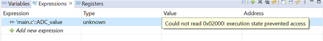
unsigned int ADC_value;
int main(void){
WDTCTL = WDTPW + WDTHOLD; // Stop watchdog timer
P1DIR |= BIT0; // setting pins to output
P4DIR |= BIT0;
PMM_unlockLPM5();
//*choose analog function for pins*
//ADC setup
SYSCFG2 |= ADCPCTL9;
ADCCTL0 |= ADCON; // TURN ON ADC
ADCCTL1 |= ADCSHP; //sampling signal source = sampling timer
ADCCTL1 |= ADCSSEL_2; // choose SMCLK
ADCCTL2 |= ADCRES_2; // 12 bit resolution
ADCMCTL0 |= ADCSREF_7;
ADCMCTL0 |= ADCINCH_9; // A9 as input
ADCIFG &= ~0x01; //clearing interrupt flag
while(1){
ADCCTL0 |= ADCENC | ADCSC; //enable and start conversion
while( (ADCIFG & ADCIFG0) == 0 );
ADC_value = ADCMEM0;
if (ADC_value > 3613) {
P1OUT |= BIT0;
P4OUT &= BIT0;
} else {
P1OUT &= BIT0;
P4OUT |= BIT0;
}
}
return 0;
}