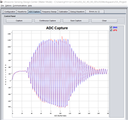
This thread has been locked.

If you have a related question, please click the "Ask a related question" button in the top right corner. The newly created question will be automatically linked to this question.

EVM430-FR6047: EVM430-FR6047 ADC PROBLEM

Part Number: EVM430-FR6047

Hi!

I get this signal.
I have a deviation towards the positive side.
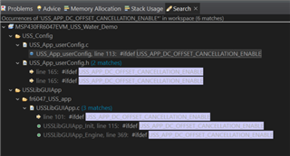
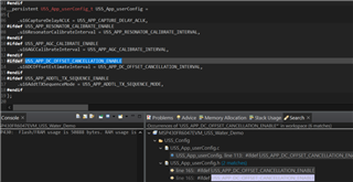
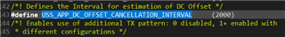
I can't find a parameter in the GUI that allows to adjust the deviation, I asked you before and you told me to look for a parameter: USS_APP_DC_OFFSET_CANCELLATION_TABLE
But it is not in the sample code.

I would appreciate it if you could help me correct this deviation.
I'm just pointing out that there is no set-up problem on the pipe


  • Hi Ido,

    Looking back at my old responses, it looks like I must have copied the wrong define.

    USS_APP_DC_OFFSET_CANCELLATION_ENABLE looks like the correct define here, which I can find in the demo code.

  • Yes, I found it now
    But it exists in several places in DEMO and I tried to change it in all of them and look for where it is changed, and it didn't do anything in ADC.

    Can you direct me more how to use this parameter?

    These are the searches:

    This is the value in the user_config.h file, I don't understand how to use it.

  • Hi Ido,

    Are you familiar with using #ifdef, #endif, etc? These are just if-else statements that are evaluated at compile time to determine whether a section of code will be compiled.

    When you perform the search, as you've done in your screenshots, you should find a line that shows 

    //#define USS_APP_DC_OFFSET_CANCELLATION_ENABLE

    Inside of USS_App_userConfig.h. Is it possible that you changed or deleted this line while working on your code? In the default, unedited project, this appears on line 113 of that file. 

    To enable that define, you should only need to uncomment that line. Once you have done this, you can build your project, and all of the code inside of the #ifdef USS_APP_DC_OFFSET_CANCELLATION_ENABLE sections will be compiled, enabling that feature. This should be visible to you inside of CCS by those sections no longer being highlighted/grayed out

  • So what should I expect to happen?
    Where do I enter the value of how much DC OFFSET to give to the signal?

  • Example:
    I change this value to 2000 and I don't see any change in the offset

  • I believe that the DC offset cancellation is applied in the USS algorithm, so you would not see it change in the ADC capture. 

    Checking around for specifics on how to set the offset cancellation interval, I found only this. Based on that post, it sounds like the exact number you put there is not that important, more than you do it at some interval. It seems to just represent how often the offset is calculated.

  • So you say it is a certain algorithm designed to make intervals to lower the DC OFFSET of the ADC?

    Because as I sent you, I set it to 2000 which is a large value as stated in the link you sent, and it still hasn't changed anything for me..
    Could it be that it always affects?

  • I am saying that the interval value that you apply is just how many measurements occur between each estimation of the DC offset. So your device will only re-calculate the necessary offset every 2000 measurement cycles once you've uncommented the //#define USS_APP_DC_OFFSET_CANCELLATION_ENABLE line in the project. However the DC offset will be applied to every measurement, not every 2000, just to be clear.

    Are you saying that you are seeing no difference in the absolute ToF calculation, or are you saying there is no change in the ADC capture? We would only expect a difference to be visible in the absolute time of flight.

    Also, to circle back to your first question, enabling DC offset calculation and usage results in an algorithm being applied to your ADC capture after receiving the raw ADC data, before the data is used to calculate the absolute time of flight. So yes it lowers the DC offset but it does not involve any change to the ADC, just to the processing of the data after it is collected.

  • Thanks for the explanation, it's much clearer now.

    Now I will explain the problem I think,
    If the ADC has an offset, then my signal starts with high values (150-250 and above for example) and then I have to increase the threshold to have normal readings and not spikes to 10000 like I used to have.


    So if it doesn't change the ADC I will still get spikes if I don't increase the threshold?
    Or because the calculation changes so it affects it?

  • The DC offset algorithm takes place after the ADC data is collected, but before the USS algorithm runs. So my expectation is that you will no longer have issues related to the DC offset, or at the least your issues would be reduced. So I would also expect that you don't have to set the envelope setting threshold extremely high to get correct time of flight readings.

    What have you been setting your envelope setting threshold to, and how do your time of flight results look? Additionally, what is your programmable gain set to?

    Your signal does not appear to be very noisy, which is good. I assume that your DC offset on your ADC signal is due to a high programmable gain. Could you try reducing your programmable gain to see if this reduces the offset, but still allows for good time of flight readings? I am aware that in the past I have recommended that you achieve an amplitude of around 900 ADC codes. This is a suggestion, but you should experiment with lower programmable gain, and lower captured amplitude, to see if this reduces your DC offset and improves your time of flight results as well. Let me know if you try this out and how it goes for you. It is possible that you may just need to leave things the same and apply the DC offset as we have been working on during the extent of this thread.

  • Look, I'm never at offset 0.
    Even if I use a narrow pipe, and in all ideal conditions I get an offset of 50-70 (after using the gain to get a signal around the 800 amplitude).
    In such cases I use a threshold of 10-15.

    But there are cases when the pipe is wider and the system is a little more difficult for signal passage (pipes made of different materials and different thickness)
    In such cases I have to balance between a strong signal and a low offset.
    Because if I increase my signal to the 800 amplitude area, my offset can reach 200-300 and then I have to raise the threshold to the 30-35 area.
    In such cases I am debating whether to both raise the threshold and use the DC OFFSET algorithm?

  • In those cases, yes I would recommend that you do both.

    Are you using a clamp-on style meter?

    If you need to use high programmable gain, then you will likely always see some offset, and in that case you will probably need to use both solutions to address the time of flight issues as mentioned above. You will need to experiment to find the conditions that work best for your application.

**Attention** This is a public forum