


HI teams:
In the MSP430FR5994 chip, if I want to use the DMA module to receive the data sent back by the sampling chip, how should the DMA bottom layer be configured correctly?
Problem background:
I want to collect data from 8 boards. When I request data, I request it one board at a time. Currently, the communication between my MSP430 and the sampling chip is SPI communication. When the SPI in the MSP430 receives the data, UCB2RXIFG is established. Using this flag as the trigger source of DMA, DMA starts to transfer the data from the SPI receiving buffer to the voltdest_buff array I set, and then I will extract the valid data in the array for subsequent processing.
Problem Description:
According to the above description, the whole process is for the host to send the data request frame of board No. 1. After the acquisition chip No. 1 responds, the SPI receiving flag is established, and the DMA starts to move data. After waiting for a certain period of time, the host starts to send the data request frame of board No. 2, and the acquisition chip No. 2 After the chip responds, DMA starts to move data, wait for a certain period of time, and the host starts to send No. 3... This cycle continues until all the board data is read. I now find that if the voltdest_buff array size is set to the size of the data returned by one board. The size of the array will cause the data in the array to be out of order (the data is correct, but the order is wrong). If the size of the voltdest_buff array is set to the total size of the data returned by 6 boards, the array will have data coverage. The initial data of the array It's messy, but if you look down, you can find the complete data valid frame.
Doubtful points:
(1) Using UCB2RXIFG as the trigger source for DMA transfer will cause the timing of DMA transfer to be uncontrollable. I still don’t know how to solve it. How should the timing be controlled?
(2) Using DMAREQ as the trigger source for DMA transfer, the transfer has not been successful. I don’t know how to modify my configuration correctly. I understand that using DMAREQ as the trigger source will make the entire transfer process controllable.
My configuration is as follows:
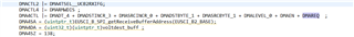
Do you have any better suggestions or routine reference?
I look forward to your reply, thank you
