This thread has been locked.

If you have a related question, please click the "Ask a related question" button in the top right corner. The newly created question will be automatically linked to this question.

MSP430F67661A: Maximum and Minimum voltages can be read through MCU

Part Number: MSP430F67661A

Dear Team,

I have been engaged in measuring AC three-phase using MSP430.

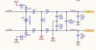
Could you please provide information on the minimum and maximum differential voltage that can be read via SDXP0 and SDXN0?

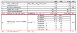
I need to measure a voltage range from a minimum of 5V to a maximum of 790V (peak to peak). 

  • Hi Praveen,

    The differential between the inputs can be ± the values listed in the datasheet. The section you highlighted is if you use an external reference, your input range of Vin = Vainxp - Vainxn = ±930 mV (if positive terminal is 250mV and negative terminal is -250mV your total Vin is 500mV).

    The parameter above is with the internal reference but the spec is read similarly.

    With your 790V you will want to voltage divide that down to the gain setting you want, for gain = 1, this is 930mV.

    Regards,
    Luke

  • Dear Luke Ledbetter, 

    Thanks for the reply, I got a bit confused. Let's simplify. 

    1. What will be the minimum differential voltage I can measure through SDXP0 and SDXN0 pins? With the Gain 1? 

  • Hi Praveen,

    With a gain of 1 the minimal differential voltage is -930mV and max is 930mV.

    Are you wanting to know the minimum difference between the 2 inputs to see a notable code difference?

    Regards,

    Luke

  • Hi Luke Ledbetter,

    Thanks for your input, 

    Bascily I want to measure the current range 0 to 5A, Below is my analog front end for the CT, 

    CUR3_P and CUR3_N are connected to the MSP430. 

    1. As you said, What will be the minimum voltage that can be measured via Sigma delta ADC?

    2. What will be the minimum current that we can measure over ADC? Is it possible to measure 10mA? 

  • Hi Praveen,

    From the user's guide data format the max and min values are based on your FSR, which is dependent on your reference voltage.

    I recommend reading the Implementation of a 3-phase electronic meter as it can go into some of these details on the total process as well as design considerations.

    For the current reading, it depends on your design and what you use (Current Transformers, Rogowski coils, Shunt). It will detect something at 10mA, but the accuracy will vary. There is a results section in the linked document, the testing was down to 0.05 Amps.

    Regards,

    Luke

**Attention** This is a public forum