This thread has been locked.

If you have a related question, please click the "Ask a related question" button in the top right corner. The newly created question will be automatically linked to this question.

MSP430I2040: Excessive power consumption when supposed to be in LPM4.5

Part Number: MSP430I2040
Other Parts Discussed in Thread: ENERGYTRACE

Hi,

We have a sensor built around MSP430I2040. While trying to optimize its power consumption, I noticed that it draws on average 22uA when it is instructed to stay in LPM4.5.

It is quite a simple circuit as depicted below. MSP430I2040 wakes up to external interrupt on P2.1, stays in LPM4.5 if P2.1 remains low.

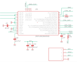
The following current trace is measured through the EnergyTrace++ tool  that came with SimpleLInk Dev boards. All external parts that connect to positive power supply (VCC) has been removed, so only MSP430I2040, and RST pin through a pullup resistor is connected to VCC.

The overall current consumption being about 20uA indicates system does enter into LPM4.5, otherwise the current consumption will be > 70uA if in LPM4 as stated in datasheet. But the zoomed out current trace indicates frequent high current draw as much as 250uA. 

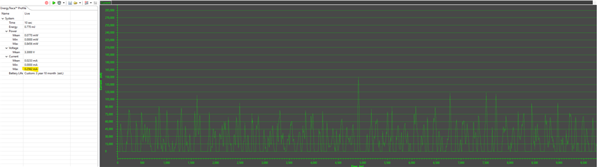
I don't think this is an artifact of measurement, because we usually get good and expected results when measuring SimpleLink MCU based systems. I also don't think this is caused by some leak in the peripheral circuit or PCB itself, because in that case, there should be steady floor of current draw.

My suspicion is that somehow, probably because the voltage on P2.1 is not stable, therefore system may attempt to exit LPM4.5 but then immediately goes back into LPM4.5. What could be the other sources of current draw?

Thanks,

ZL

  • Hi ZL,

    I think this need further debug to figure out what happen in your board.

    1. Do not use interrupt to wake up the device, and check whether the current consumption is normal with keep the LP4.5.

    2. Do some delay when device is waked up by interrupt, and check whether the current has the high current consumption with the delay.

    B.R.

    Sal

  • Hi Sal,

    I disabled the interrupt on P2.1 so system won't wake up at all, but the average current draw and trace shape remain the same. I guess this is not caused by interrupt.

    All the unused GPIO pins have already been set to output low, UART and timers are also turned off before entering into LPM4.5. 

    Do you have any ideas where the residual current draw could come from?

    Thanks,

    ZL

  • Hi ZL,

    All the unused GPIO pins have already been set to output low,

    I suggest you can set the GPIO as input or output high-impedance for unused pin.

    Furthermore, I suggest you can only set all GPIO as input, and let PCU enter LP4.5, then check the current consumption. If it still have the issue, I assume it related to external circuit. If the issue disappear, you can then add modules one by one, to check what happens here.

    B.R.

    Sal

  • Hi Sal,

    I removed the MCU from the PCB and measure current draw again. The result is interesting. While the overall/average current draw decreased to 1uA, the peak current draw still reaches up to 250uA. I guess the 20uA also current draw does originate from MCU.

    There doesn't seem to be anything obvious. We will build another version of this sensor board with FR series MCU and see what kind of numbers we can get.

    Thanks for your input, I will mark this question as resolved for now.

    Best,

    ZL

**Attention** This is a public forum