MSP430F5308: Rev E and Rev F errors

Part Number: MSP430F5308

Hi All,

I have a MSP430F5308 Rev. E board and a Rev. F board, but the Rev. E  has an error.

The errors are as follows.

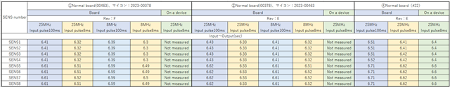
1,After receiving the INPUT signal, the OUTPUT signal is output in 6.39s or 6.59s, but in 6.28s or 6.48s[-110ms].

2、When the waveform of DCO was measured with an oscilloscope, no error was found.
There is no error in the peripheral board.

3,Error occurs 40% of the time.

The main settings of taimer.
・Time is counted by Timer_A.
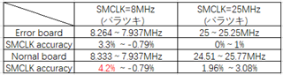
・SMCLK = 6.25MHz
・Up mode


We will send you the firmware, so please approve the private mode.

Best Regards,

Ito

  • Hi Ito

    >> I have a MSP430F5308 Rev. E board and a Rev. F board

    May I confirm this board is user-design board?

    on the difference between MCU version E and F, Please check MSP430F5308 Microcontroller Errata (Rev. AC)

    but I haven't found the difference on timer. is this issue related with BSL? I don't think so

    >> After receiving the INPUT signal, the OUTPUT signal is output in 6.39s or 6.59s, but in 6.28s or 6.48s[-110ms].

    Could you please share some waveform to me to understand this issue?

    Thanks

  • Hi Li

    Thank you for your reply.

    This board is user-design board.

    I don't think BSL can be the cause.

    May I accept your Friendship and contact you personally to send you customer data?

    Best Regards,

    Ito

  • Hi Ito

    I have accept the friendship

    Thanks

  • Hi Li

    I have sent you a private message, please check it.

    Best Regards, 

    Ito

  • Hi Ito

    I have the received customer_file.xls. I need time to check in the detailed.

    Thanks

  • Hi Ito

    I checked the 242228_SMCLK確認 sheet of customer_file.xls.

    used has tested SMCLK through P2.2 on error board and normal board. The 8MHz and 25MHz frequency on error board should be normal 8.264~7.937MHz and 25~25.25MHz

    I understand the issue on error board is ~6 second based on SMCLK.

    I checked the code briefly. I can see print_nout and print_out are used on the code.

    I am not sure this print function can impact the timming.

    Please check with customer if the issue will happen if remove the print function.

    Thanks

  • Hi LI

    Thank you for investigating.

    I am currently having it checked regarding print_nout and print_out.

    We will explain the current situation.

    1, I checked if the error is transferred by replacing Rev.E and Rev.F.
    2, As a result, the error is not transferred, and the error is sometimes on the board and sometimes not on the board.
    3, Next, the clock was set to 25MHz and the input pulse width was changed from 100ms to 8ms, and it became normal.
    4, The cause may be the input pulse width.

    [Question]
    Is there any cause for the input pulse width to cause a difference in the time from input to output?
    If there is a possibility that the microcontroller is the cause, please let me know.

    Best regards,

    Ito

  • Hi LI

    How is your progress?
    My client is in a hurry to respond.
    Any reply would be appreciated.

    Best Regards,

    Ito

  • Hi Ito

    >> Is there any cause for the input pulse width to cause a difference in the time from input to output?
    >> If there is a possibility that the microcontroller is the cause, please let me know.
    I have checked the xls file and the code, but I can't find the possible cause and possible cause from MCU.

    >> I have a MSP430F5308 Rev. E board and a Rev. F board, but the Rev. E  has an error.
    >> As a result, the error is not transferred, and the error is sometimes on the board and sometimes not on the board.
    I think the problem happens on MSP430F5308 Rev. E compared with MSP430F5308 Rev. F.
    Could you please explain if the same board has been tested using Rev.E and Rev.F MCU device.
    Could you please provide the picture of MCU with mark and the picture of board?

    >> Next, the clock was set to 25MHz and the input pulse width was changed from 100ms to 8ms, and it became normal.
    Could you please explain more on this issue?

    >> on the fREF acurracy, I think it should better to check fREF directly if the frequency is compliant with data sheet or not.
    Please consider using MSP430F530x_UCS_02.c on www.ti.com/.../SLAC469 to test the fREF


    >> I check the user code, I can find the code setting 25MHz, Could you please comment the code lines to set DCO to 8MHz
        UCSCTL3 = SELREF_2;         // Set DCO FLL reference = REFO
        UCSCTL4 |= SELA_2;          // Set ACLK = REFO

        __bis_SR_register(SCG0);    // Disable the FLL control loop
        UCSCTL0 = 0x0000;           // Set lowest possible DCOx, MODx
        UCSCTL1 = DCORSEL_7;        // Select DCO range 50MHz operation
        UCSCTL2 = FLLD_1 + 762;     // Set DCO Multiplier for 25MHz
                                    // (N + 1) * FLLRef = Fdco
                                    // (762 + 1) * 32768 = 25MHz
                                    // Set FLL Div = fDCOCLK/2
        __bic_SR_register(SCG0);    // Enable the FLL control loop

        // Worst-case settling time for the DCO when the DCO range bits have been
        // changed is n x 32 x 32 x f_MCLK / f_FLL_reference. See UCS chapter in 5xx
        // UG for optimization.
        // 32 x 32 x 25 MHz / 32,768 Hz ~ 780k MCLK cycles for DCO to settle
        __delay_cycles(782000);

        // Loop until XT1,XT2 & DCO stabilizes
        // In this case only DCO has to stabilize
        do {
            // Clear XT2,XT1,DCO fault flags
            UCSCTL7 &= ~(XT2OFFG + XT1LFOFFG + DCOFFG);
            SFRIFG1 &= ~OFIFG;      // Clear fault flags
        } while (SFRIFG1&OFIFG);    // Test oscillator fault flag

    >> Error occurs 40% of the time.
    How many unites of MCU has been tested.
    May I confirmed if this issue only happens on Rev. E MCU?
    May I confirmed if this issue only happens on 25MHz DCO clock?

    Thanks!

  • Hi LI

    Thank you for investigating.

    There are two boards, Rev.E board and RevF board.
    And after SWAP inspection, the MCU is replaced.

    >> Next, the clock was set to 25MHz and the input pulse width was changed from 100ms to 8ms, and it became normal.
    Could you please explain more on this issue?
    >>
    I got the following result.
    Input: 8 msec width → Time difference: 6.52 sec.
    Input: 100 msec width → Time difference: 6.61 sec.
    Input: 200 msec width→ Time difference: 6.71 sec.
    Input: 300msec width → Time difference: 6.81sec
    Input: 400msec width → Time difference: 6.91 sec.
    Input: 500msec width → Time difference: 7.01sec

    I have verified the accuracy of fREF and there seems to be no problem.

    >> I check the user code, I can find the code setting 25MHz, could you please comment the code lines to set DCO to 8MHz

    We will send you the code for the 8 MHz configuration as soon as we receive it from the customer.

    >>May I confirmed if this issue only happens on Rev. E MCU?
    >>May I confirmed if this issue only happens on 25MHz DCO clock?

    →My customer had a SWAP inspection, and both RevE and RevF showed errors.
    →Errors were confirmed for both 25MHz and 8Mhz.

    Please see the table below for details

    I sent the photos in a private message.

    Best Regards,

    Ito

  • Hi Ito

    Thanks for your detailed information!

    >> I have verified the accuracy of fREF and there seems to be no problem.

    May I confirmed you have verified the accuracy of fREF on both rev E and rev F?

    if yes. it means there is no issue (Violation of manual) on fREF (REFO frequency).

    So, the customer suspects which perpherial possibly has issue? 

    Thanks!

  • Hi LI

    Yes, both have been checked for clock accuracy.

    Now the customer thinks there is a problem with the input pulse width.
    Please see the table I sent you for details.
    That the output time depends on the input pulse width,
    IES register edge detection may not work properly.

    Best Regards,

    Ito

  • Hi Li,

    Did you get any information on this?

    Best Regards,

    Ito

  • Hi Ito

    >> Now the customer thinks there is a problem with the input pulse width

    May I know which device the input pulse is coming from?

    >> Did you get any information on this?

    So far, I don' have idea on this issue cause

    I have ordered MSP430F5308 (should be revison F) try to reproduce this issue

    Thanks

  • Hi Li,

    I sent the schematic and description in a private message.

    Please check this message.

    Best Regards,

    Ito

  • Hi Ito

    Thanks! I will study it

    Please kinldy understand I need some time to study the material and check if there is any approach.

    BTW, I have gotten the MSP430F5308 which is revison F

    Thanks

  • Hi Li,

    Thank you for your cooperation.

    Ito

  • Hi Li,

    Please let me know current progress.

    Is there any other data you want?

    Best Regards,

    Ito

  • Hi Ito

    >> Please let me know current progress.

    I can't find the good method to reproduce the issue using  revison F MSP430F5308.

    So, I focus on studying and checking the detailed test result from user sides

    I studied "[クロック精度の調査結果]" on customer_file.xls file.

    I think DCOCLK accuarcy is matched with the specification on DS (3.5% full temperature and 1.5% at 2C)

    >> Please see the table I sent you for details.
    >> That the output time depends on the input pulse width,
    >> IES register edge detection may not work properly.

    I checked the waveform on customer_file.xls file. but, I think I haven't understood exactly this possible problem.

    Could you please explain the detailed on the "IES register edge detection may not work properly."

    Could you please kindly point the feature description on the user's guide?

    >> This is the temperature curve.Temperature.pdf

    Could you please explain more the this curve?

    >> I sent the schematic and description in a private message.

    "TRIG" is the connector for the signal input to the board on which the microcontroller is mounted.

    Could you please comment which MCU pin is connected with "TRIG" signal?

    Thanks!

  • Hi Li,

    >>I think DCOCLK accuarcy is matched with the specification on DS (3.5% full temperature and 1.5% at 2C)

    I am thinking that if all 12780 counts are shifted by 3.5% or 1.5%, they will be shifted by -223.65ms or -95.85ms.
    I think it is unlikely that all clocks would be shifted.

    >>Could you please explain the detail on the "IES register edge detection may not work properly."

    With the PxIES register being level detection instead of edge detection,
    This is because we thought that the output time may be changing with the input pulse width.
    However, according to the user's guide, interrupts are edge detected (high to low), so we believe this is not a problem.

    [12.2.7 Port Interrupts]
    MSP430x5xx and MSP430x6xx Family User's Guide (Rev. Q) (ti.com)

    >>Could you please explain more the this curve?

    This is the E2E support material you are responsible for elsewhere.
    Please check this one as well.

    MSP430FR2355: Get the same ADC value for a certain interval. - MSP low-power microcontroller forum - MSP low-power microcontrollers - TI E2E support forums

    >>"TRIG" is the connector for the signal input to the board on which the microcontroller is mounted.
    Could you please comment which MCU pin is connected with "TRIG" signal?

    TRG1→P1.0
    TRG2→P1.1

    TRG1" is a signal to start monitoring sensors 1 to 4, and "TRG2" is a signal to start monitoring sensors 5 to 8.

    Best Regards,

    Ito

  • Hi Li,

    Please let me know current progress.

    Is there any other data you want?

    Best Regards,

    Ito

  • Hi Ito

    >> Xiaodong: I think DCOCLK accuarcy is matched with the specification on DS (3.5% full temperature and 1.5% at 2C)

    >> Ito: I am thinking that if all 12780 counts are shifted by 3.5% or 1.5%, they will be shifted by -223.65ms or -95.85ms. I think it is unlikely that all clocks would be shifted.

    I checked the 242228_SMCLK確認 of customer_file.xls and the code

    May I confirm if SMCLK is from DCO and FLL based on REFO and the voltage and tempreture condition of this test?

    Suppose the votage and tempreture condition is 1.8 V to 3.6 V and the Full temperature range, the REFO error should be ±3.5%

    But the SMCLK accuracy on error board is less than ±3.5% and the SMCLK accuracy on normal board is larger than 3.5% at 8MHz

    as our previous discussion, could you please clearify this test?

    I think we can focus on the SMCLK frequency firstly because others test on SENS1 and SENS2 is related with board, timer and Port Interrupts.

    Thanks

**Attention** This is a public forum