This thread has been locked.

If you have a related question, please click the "Ask a related question" button in the top right corner. The newly created question will be automatically linked to this question.

EVM430-FR6047: MSP430FR 6047 : ADC Reading issue I can't able to read from 0, the starting value is 2098 it was not going below that.(12Bit ADC)

Part Number: EVM430-FR6047

#include <msp430.h>

unsigned int ADC_value;
int main(void)
{
	WDTCTL = WDTPW | WDTHOLD;	// stop watchdog timer
//-----------

	P2SEL1 |= BIT2;
	P2SEL0 |= BIT2;

	PM5CTL0 &= ~LOCKLPM5;


	//----ADC CONFIG
	ADC12CTL0 &= ~ADC12SHT0;

	ADC12CTL0 |= ADC12SHT0_2;

	ADC12CTL0  |= ADC12ON;  //adc on

	ADC12CTL1 |= ADC12SSEL_2;  //selects clk

	ADC12CTL1 |= ADC12SHP;

	ADC12CTL2 &= ~ADC12RES;
	ADC12CTL2 |= ADC12RES_2;  // select resolution as 12bit

	ADC12MCTL0 |= ADC12INCH_14; // channel that im readin ADC from

	ADC12IER0 |= ADC12IE0;
	__enable_interrupt();

	while(1)
	{
	    ADC12CTL0 |= ADC12ENC | ADC12SC;  //start conversion

	    while (( ADC12IFG0 & ADC12IFG0)==0); //interrupt flag


	}
}
//------ISR
#pragma vector = ADC12_VECTOR
__interrupt void ADC12_ISR()
{
    ADC_value = ADC12MEM0;
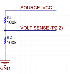
}


This is my ADC read code from the Pin 2.2 
the minimum ADC value im getting from P2.2 starts from 2098 - 4095

its not reducing while i try to reduce below 2098 (using trim pot)


If i apply the basic ADC formula for voltage i can only read from 1.7V - 3.3V

i cant able to read beteween 0v-1.69v ~ need some suggestions i cant able to find what error occurs

Please help me out

  • Hi Aravind,

    Are you using EVM board? P2.2 in the EVM board has been connected to other circuits.

    If you are using customized board, please make sure there is no other circuit connected to P2.2. Can you share the waveform of P2.2 if you ouput 1V to this pin?

    B.R.

    Sal

  • Yes Im using customized board. Unfortunately i cant able to provide the waveform because im reading the pin 2.2 within my board and i will see values using debugger mode watch window / UART . 


    is there anyother information do i need to provide ?

  • Hi Aravind,

    I think it necessary to check whether there is some issue with your curcuit, if the input of P2.2 has wrong input, then you can not get the result you want.

    Can you share the schematic of the P2.2 and related circuit?

    According the code, it seems no issue.

    B.R.

    Sal

  • Hi, 

    1.MSP6047 is powered by battery source 3.6V, I'm trying to read the voltage from same battery source which MSP6047 is powered.

    2.MSP6047 is functiong till batery voltage drops to 2.2V.

    I'm not able to read the exact battery voltage.Give me some examples and suggestions to overcome this problem.

  • According to your schematic, the adc input voltage should be 1.1~1.8V due to resistor voltage division.

    Meanwhile, due to you are using VCC as ADC referencr, the adc result should be always around 1/2 * 4095 = 2047

    Please use stable voltage as adc reference:

    B.R.

    Sal

  • I have Tried assuming ADC12VRSEL_0 register .

    But it still not decreasing below the voltage range 1.8v 

    Is there any other way around?

  • Hi Aravind,

    You can refer to below example for internal reference setting for adc sampling:

    https://dev.ti.com/tirex/explore/node?a=IOGqZri__3.80.13.03&a=a3PaaoK__1.10.01.05&node=A__ALFdeSTsbBitEKxYO01hmw__msp430ware__IOGqZri__LATEST&r=a3PaaoK__1.20.00.05&r=a3PaaoK__1.20.01.06&search=ADC 

    Can you share the details below:

    What are the adc conversion results with SOURCE VCC = 3.3V (please use VCC as reference and also internal reference 2.0V)?

    What are the adc conversion results with SOURCE VCC = 2.2V (please use VCC as reference and also internal reference 2.0V)?

    And then we can check out what happens here. 

    BTW, the code:

    while (( ADC12IFG0 & ADC12IFG0)==0);

    Seems not proper, "ADC12IFG0 & ADC12IFG0" seema always output "1", so it will repeatedly start adc when adc sampling has not ended.

    B.R.

    Sal

  • Hi Sal Ye

    when source VCC 3.3 i can able to read voltage from resistor divider (1.5 to 1.6V)

    When source vcc drops to 2.2V i cannot able to read the voltage from resistor divider

  • Hi Aravind,

    I may ask you use the example code:

    Can you give the directly result of ADC conversion, it should be 12-bit data from 0-4095.

    What the data if you use VCC as ADC reference? 

    What the data if you use internal 2.0V as ADC reference?

    When source vcc drops to 2.2V i cannot able to read the voltage from resistor divider

    I can try it with a EVM board, it seems incorrect. Please try the example code firstly and give me some feedback.

    B.R.
    Sal

  • 
    #include <msp430.h>
    
    int main(void)
    {
        WDTCTL = WDTPW | WDTHOLD;               // Stop WDT
    
       
        P2SEL1 |= BIT2;                         // Configure P2.2 for ADC
        P2SEL0 |= BIT2;
    
        // Disable the GPIO power-on default high-impedance mode to activate
        // previously configured port settings
        PM5CTL0 &= ~LOCKLPM5;
    
        // By default, REFMSTR=1 => REFCTL is used to configure the internal reference
        while(REFCTL0 & REFGENBUSY);            // If ref generator busy, WAIT
        REFCTL0 |= REFVSEL_1 | REFON;           // Select internal ref = 2.0V
                                                // Internal Reference ON
    
        // Configure ADC12
        ADC12CTL0 = ADC12SHT0_2 | ADC12ON;
        ADC12CTL1 = ADC12SHP;                   // ADCCLK = MODOSC; sampling timer
        ADC12CTL2 |= ADC12RES_2;                // 12-bit conversion results
        ADC12IER0 |= ADC12IE0;                  // Enable ADC conv complete interrupt
        ADC12MCTL0 |= ADC12INCH_14 | ADC12VRSEL_2; // A1 ADC input select; Vref=1.2V
    
        while(!(REFCTL0 & REFGENRDY));          // Wait for reference generator
                                                // to settle
    
        while(1)
        {
            __delay_cycles(5000);               // Delay between conversions
            ADC12CTL0 |= ADC12ENC | ADC12SC;    // Sampling and conversion start
    
            __bis_SR_register(LPM0_bits + GIE); // LPM0, ADC10_ISR will force exit
            __no_operation();                   // For debug only
        }
    }
    
    #if defined(__TI_COMPILER_VERSION__) || defined(__IAR_SYSTEMS_ICC__)
    #pragma vector = ADC12_B_VECTOR
    __interrupt void ADC12_ISR(void)
    #elif defined(__GNUC__)
    void __attribute__ ((interrupt(ADC12_B_VECTOR))) ADC12_ISR (void)
    #else
    #error Compiler not supported!
    #endif
    {
        switch (__even_in_range(ADC12IV, ADC12IV__ADC12RDYIFG))
        {
            case ADC12IV__NONE:        break;   // Vector  0:  No interrupt
            case ADC12IV__ADC12OVIFG:  break;   // Vector  2:  ADC12MEMx Overflow
            case ADC12IV__ADC12TOVIFG: break;   // Vector  4:  Conversion time overflow
            case ADC12IV__ADC12HIIFG:  break;   // Vector  6:  ADC12BHI
            case ADC12IV__ADC12LOIFG:  break;   // Vector  8:  ADC12BLO
            case ADC12IV__ADC12INIFG:  break;   // Vector 10:  ADC12BIN
            case ADC12IV__ADC12IFG0:            // Vector 12:  ADC12MEM0 Interrupt
                if (ADC12MEM0 >= 0x6B4)         // ADC12MEM = A1 > 0.5V?
                    P1OUT |= BIT0;              // P1.0 = 1
                else
                    P1OUT &= ~BIT0;             // P1.0 = 0
                __bic_SR_register_on_exit(LPM0_bits); // Exit active CPU
                break;                          // Clear CPUOFF bit from 0(SR)
            case ADC12IV__ADC12IFG1:   break;   // Vector 14:  ADC12MEM1
            case ADC12IV__ADC12IFG2:   break;   // Vector 16:  ADC12MEM2
            case ADC12IV__ADC12IFG3:   break;   // Vector 18:  ADC12MEM3
            case ADC12IV__ADC12IFG4:   break;   // Vector 20:  ADC12MEM4
            case ADC12IV__ADC12IFG5:   break;   // Vector 22:  ADC12MEM5
            case ADC12IV__ADC12IFG6:   break;   // Vector 24:  ADC12MEM6
            case ADC12IV__ADC12IFG7:   break;   // Vector 26:  ADC12MEM7
            case ADC12IV__ADC12IFG8:   break;   // Vector 28:  ADC12MEM8
            case ADC12IV__ADC12IFG9:   break;   // Vector 30:  ADC12MEM9
            case ADC12IV__ADC12IFG10:  break;   // Vector 32:  ADC12MEM10
            case ADC12IV__ADC12IFG11:  break;   // Vector 34:  ADC12MEM11
            case ADC12IV__ADC12IFG12:  break;   // Vector 36:  ADC12MEM12
            case ADC12IV__ADC12IFG13:  break;   // Vector 38:  ADC12MEM13
            case ADC12IV__ADC12IFG14:  break;   // Vector 40:  ADC12MEM14
            case ADC12IV__ADC12IFG15:  break;   // Vector 42:  ADC12MEM15
            case ADC12IV__ADC12IFG16:  break;   // Vector 44:  ADC12MEM16
            case ADC12IV__ADC12IFG17:  break;   // Vector 46:  ADC12MEM17
            case ADC12IV__ADC12IFG18:  break;   // Vector 48:  ADC12MEM18
            case ADC12IV__ADC12IFG19:  break;   // Vector 50:  ADC12MEM19
            case ADC12IV__ADC12IFG20:  break;   // Vector 52:  ADC12MEM20
            case ADC12IV__ADC12IFG21:  break;   // Vector 54:  ADC12MEM21
            case ADC12IV__ADC12IFG22:  break;   // Vector 56:  ADC12MEM22
            case ADC12IV__ADC12IFG23:  break;   // Vector 58:  ADC12MEM23
            case ADC12IV__ADC12IFG24:  break;   // Vector 60:  ADC12MEM24
            case ADC12IV__ADC12IFG25:  break;   // Vector 62:  ADC12MEM25
            case ADC12IV__ADC12IFG26:  break;   // Vector 64:  ADC12MEM26
            case ADC12IV__ADC12IFG27:  break;   // Vector 66:  ADC12MEM27
            case ADC12IV__ADC12IFG28:  break;   // Vector 68:  ADC12MEM28
            case ADC12IV__ADC12IFG29:  break;   // Vector 70:  ADC12MEM29
            case ADC12IV__ADC12IFG30:  break;   // Vector 72:  ADC12MEM30
            case ADC12IV__ADC12IFG31:  break;   // Vector 74:  ADC12MEM31
            case ADC12IV__ADC12RDYIFG: break;   // Vector 76:  ADC12RDY
            default: break;
        }
    }
    

    Used this code i set internal voltage ref to 2.0v it still reads the same value not decreasing below 2048

  • What is the read value?

    The formula should be VCC/2/2.0*4096, which means

    3.3V -> around 3072

    2.2V -> around 2252

    B.R.

    Sal

  • i set for 2.0v 

  • It is not recommended use VCC=2.0V when use internal 2.0V reference. (because internal reference module shouldn't be boost circuit, 2.0 VCC might have some random noise make it voltage drop out).

    Please try little higher VCC input, such as 2.2V, 2.4V. And then check whether it is okay with the result.

    B.R.

    Sal

  • I tried changing the ADC12VRSEL_2 register 


    while(REFCTL0 & REFGENBUSY); // If ref generator busy, WAIT
    REFCTL0 |= REFVSEL_2 | REFON; // Select internal ref = 2.5V
    // Internal Reference ON 

    and added these steps seems like my adc read value stays the same i got 2114 
    is there any other way to fix the internal reference voltage sir??

  • Hi Aravind,

    From my perspective, it seems the VREF module are not working normally.

    I will be out of office for several days. Let me do a test based on a similar board next week.

    If you find anything new, you can sync here and let me aware. Thanks for your patience.

    B.R.

    Sal

**Attention** This is a public forum