This thread has been locked.

If you have a related question, please click the "Ask a related question" button in the top right corner. The newly created question will be automatically linked to this question.

MSP430FR6928: Issues with linker command and .ti.noinit

Part Number: MSP430FR6928
Other Parts Discussed in Thread: MSP430FR6989

I tried to post this as a Code Composer Studio issue but I was brought to this forum

I wrote an application where I collect data from different sources (e.g. a2d, timer calculations, etc.) and I place the collected data as an object of a structure. Then I create an array of these structures.
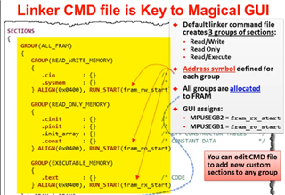
I'm using an MSP430FR6928. For starters, the array had about 100 objects. The linker command I used was the default created by CCS. The original array was placed in FRAM.
Then I modified the code so as to place the array and an index variable in .ti.persistent section. No problem there either. (The default linker places the .ti.persistent section in FRAM).
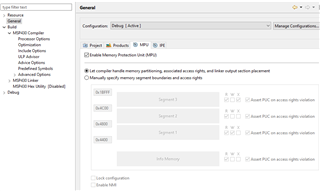
Then I modified the placement of the .ti.persistent section and I moved the array and the index variable (an unsigned integer) to FRAM2. When I did that, first I had an error that was solved changing the memory model to LARGE (and I also changed the option of "what data must be near" to "none") . The program compiled without errors but now, when I checked the area of FRAM2 where the array was supposed to be ... it was empty. No data had been written in FRAM2 and no error messages were reported. Investigating  the section that controls MPU, I had kept the default settings created by Code Composer. I decided to disabled the MPU, and the program worked again. I would rather have the MPU active, but it seems that the system doing it automatically creates the wrong settings ...  and I'm not sure about how to configure it myself.
Finally, and this is the real reason for my post: I replaced the .ti.persistent in FRAM2 with .ti.noinit . Now the code doesn't work anymore ... I receive some error message with the word "trampoline" and I am not familiar with this concept. I thought the only difference between .persistent and .noinit was related to the initialization. I guess there is more to it? Any help on this will be appreciated.

  • Hi Carlos Yanzig

    Please review the MPU setting based on MSP430FR58xx, MSP430FR59xx, and MSP430FR6xx Family User's Guide (Rev. P) and the setting on CCS

    Thanks

  • I'm not quite sure what your goal is but:

    1) TI.noinit is normally placed in RAM (for reasons I don't know about). To put it in FRAM, you should change the linker .cmd to move the TI.noinit specification within the READ_WRITE_MEMORY group. This allows the linker/run-time to figure out the MPU settings. Something resembling:

            GROUP(READ_WRITE_MEMORY)
            {
    
                .TI.persistent : {}              /* For #pragma persistent            */
                .TI.noinit  : {}                  /* For #pragma noinit                */
                .cio           : {}              /* C I/O Buffer                      */
                .sysmem        : {}              /* Dynamic memory allocation area    */
            } PALIGN(0x0400), RUN_START(fram_rw_start)
    

    2) To arrange for NOINIT, you need to change "Project->Properties->Debug->MSP430 Flash Settings->Erase Options" to "Erase and download necessary segments" to avoid (mass) erasing the NOINIT data.

    3) PERSISTENT data is re-initialized each time you download new code, but NOINIT is not. You should consider how to deal with first-time (not to mention corruption) for NOINIT. A checksum/CRC may be useful.

    4) The method I described in (1)-(2) will get you going, but the section is susceptible to being moved around as your program grows. If this is a concern, you probably need a separate MEMORY segment for it, which means working with both the linker .cmd and the MPU. (I don't want to make this sound harder than it is, but it's not trivial.) You may also need to do this if your NOINIT section is very large.

  • Appreciate the reply. First thing I did, I moved the .TI.persistent  section to its own section. And this section occupies almost all FRAM2. And as mentioned before, this works just fine when I disable the MPU. To be more explicit

    SECTIONS
    {
    .TI.persistent : {} > FRAM2 /* For #pragma persistent. I added this section un-grouped here */ 
    // .TI.noinit : {} > FRAM2 /* For #pragma noinit . Commented out in the case that the firmware works */

    GROUP(RW_IPE)
    {
    GROUP(READ_WRITE_MEMORY)
    {
    // .TI.persistent : {} /* For #pragma persistent I removed this entry from the group */

    My understanding from what I read in the manual, is that there is no need to mention read write because it is read and write by default. 

    Problem happens when I try to replace persistent with noinit ... That is to say:

    // .TI.persistent : {} > FRAM2 /* For #pragma persistent. I commented out the persistent section */ 
    .TI.noinit : {} > FRAM2 /* For #pragma persistent. Now I have created a data section that is left alone by the compiler*/

    GROUP(RW_IPE)
    {
    GROUP(READ_WRITE_MEMORY)
    {
    // .TI.persistent : {} /* For #pragma persistent I removed this entry from here */

     What I didn't do is point number 2) ... I'll try that next, assuming that compilation is successful. I have functions in my firmware that allow me to handle what it happens within the array. I have taken care of the issues that you mention already. 

    The section is big enough that can't be moved around. An array is a continuous chunk of memory that in this case, can't be moved around.

  • If your goal is to put your NOINIT variables at the beginning of high-FRAM (FRAM2), then, as Xiaodong mentioned, you'll need the MPU Editor (Build Settings->General->MPU[tab]). Also (by my arithmetic) you need to make sure all your code fits in low FRAM.

    The MPU only gives you 3 regions. The lowest (0x4400 on the FR6928) generally should be RW, since as you've seen the compiler/linker may expect that. (If your map says the READ_WRITE_MEMORY is empty, you can make that RX as well.) The second region -- code and read-only data -- extends through the interrupt vectors (0xFFFF) and should be RX. The third region is your data (0x10000) which should be RW.

    In the large model, .text is preferentially put in FRAM2, so you should remove FRAM2 from that line in the linker .cmd. To be safe, you should remove FRAM2 from everywhere else, though those others are unlikely to overflow.

  • Based on the recommendations in the previous reply and previous tries, I did the following:

    I ungrouped persistent and I initialized it in the linker as shown below. My array takes almost all of FRAM2 (I also have an unsigned variable in this piece of memory ... A kind of index (uint16_t). I wrote:

    .TI.persistent : {} > 0x10000

    just to make sure that the array would start at 0x10000. BTW ... the array is 49000 bytes long.

    In MPU settings, I did the following:

    I enabled MPU and went for the option of adjusting things manually. I did only one change from the options that were set already there:

    In segment 3, I specified the R and W options rather than the X option and I started this segment at 0x10000. Everything works. I also checked to increase the size of segment 3 to 0xE000. It made no difference.

    I also did the:

    "Erase Options" to "Erase and download necessary segments" as suggested. The other settings were correct already.

    When I tried the same approach, replacing PERSISTENT with NOINIT, I got a linker error saying that data didn't fit. The error was caused because I forgot to remove the initialization of the 2 variables.

    In my code I had used the #pragma PERSISTENT directive for the 2 variables and I had initialized them to 0.

    As I mentioned before this is NOT what I wanted. My goal was to keep the array and the variable undisturbed in FRAM2.

    Next I commented out .TI.persistent in the linker and replaced it with

    .TI.noinit : {} > 0x10000

    and in my code, I replaced the #pragma PERSISTENT with the #pragma NOINIT for the 2 variables mentioned previously ... this time I removed the initialization of the variables ... the tools complained about that. And that is fine with me. My program takes care of this initialization.

    The tools run fine with no complaints or warning and the FRAM2 gets initialized to 0xFFFF ... all of it. If something is written in the array it gets erased.

    So now I have the 2 options: I can apply #pragma PERSISTENT and have everything initialized by the tools or I can apply #pragma NOINIT and get everything erased to 0xFFFF ...

    BTW, the program takes about 30% of FRAM and there are less than 300 bytes allocated in RAM, according to CCS.

    Regards

  • I'm having a little trouble figuring out what you ended up with.

    When you asked earlier, I modeled what (I think) what you were trying to do, using the methods I suggested, on an FR5994 (close enough I think) and I got the results I expected -- re-loading the code didn't erase the NOINIT variables, and they were writeable. We must be doing something different.

    1) Is it correct that your (large) array does Not have an initializer, and it is attributed using #pragma NOINIT()?

    2) Did you remove the "FRAM2" reference from the .text stanza in the linker .cmd?

    3) In your .map file, does anything else show up above 0x10000 besides your array?

    4) The fact that your array is erased suggests that the linker decided the segment containing your TI.noinit section was "necessary", i.e. it was loadable. You might try something like:

    .TI.noinit : type = NOLOAD{} >FRAM2

    to explicitly ask for this. I just tried it and it succeeded, though that doesn't prove much since my program was succeeding without it.

    5) Can you post the declaration for your array and the TI.noinit line in your linker.cmd, each with a few lines of context? Maybe there's something we're both missing.

  • When you asked earlier, I modeled what (I think) you were trying to do, using the methods I suggested, on an FR5994 (close enough I think) and I got the results I expected ...

    As I mentioned before, I'm using the MSPFR6928. If they are similar I take your word. I do have a Launchpad based on the FR5994. If you want to share what you are doing, I can
    try to reproduce it.

    -- re-loading the code didn't erase the NOINIT variables, and they were writeable. We must be doing something different.

    We probably are, unless the linker command file that gets generated for the FR5994 is different or something else.

    1) Is it correct that your (large) array does Not have an initializer, and it is attributed using #pragma NOINIT()?
    I don't know what you mean by initializer ... my code does the following:

    #pragma NOINIT(Logger_Wr_Index)
    uint16_t Logger_Wr_Index;

    #pragma NOINIT(Cycle_Logger)
    Acq_Cycle Cycle_Logger[MAX_CYCLES]; // this is the structure ... 49000 bytes in size. And it gets located at 0x10000 ...

    Logger_Wr_Index is placed after the structure, even though I declare it first.

    In order to modify things in the array, the user must send commands through the serial port.

    2) Did you remove the "FRAM2" reference from the .text stanza in the linker .cmd?
    This is what I did (copied from the linker command file):

    #ifndef __LARGE_DATA_MODEL__
    .text : {} > FRAM /* Code */
    #else
    .text : {} >> FRAM | FRAM2 /* Code */
    // .text : {} >> FRAM2 | FRAM /* Code */
    #endif

    I don't know if this may have any impact in the problem. ... I can just remove it.

    3) In your .map file, does anything else show up above 0x10000 besides your array?
    I think that I just answered to that question, but here goes that piece of the map file:

    0000fffe _reset_vector
    00010000 Cycle_Logger
    0001bf68 Logger_Wr_Index
    ffffffff __TI_pprof_out_hndl
    ffffffff __TI_prof_data_size
    ffffffff __TI_prof_data_start
    ffffffff __c_args__


    4) The fact that your array is erased suggests that the linker decided the segment containing your TI.noinit section was "necessary", i.e. it was loadable. You might try something like:
    .TI.noinit : type = NOLOAD{} >FRAM2


    I can try that, and if I'm allowed by the tools I can also do:
    .TI.noinit : type = NOLOAD{} > 0x10000

    5) Can you post the declaration for your array and the TI.noinit line in your linker.cmd, each with a few lines of context? Maybe there's something we're both missing.

    MEMORY
    {
    TINYRAM : origin = 0x0006, length = 0x001A
    PERIPHERALS_8BIT : origin = 0x0020, length = 0x00E0
    PERIPHERALS_16BIT : origin = 0x0100, length = 0x0100
    RAM : origin = 0x1C00, length = 0x0800
    INFOA : origin = 0x1980, length = 0x0080
    INFOB : origin = 0x1900, length = 0x0080
    INFOC : origin = 0x1880, length = 0x0080
    INFOD : origin = 0x1800, length = 0x0080
    FRAM : origin = 0x4400, length = 0xBB80 // finishes before the area that holds INTERRUPT VECTORS, RESET, ETC.
    FRAM2 : origin = 0x10000,length = 0xBFFE  
    JTAGSIGNATURE : origin = 0xFF80, length = 0x0004, fill = 0xFFFF
    BSLSIGNATURE : origin = 0xFF84, length = 0x0004, fill = 0xFFFF
    IPESIGNATURE : origin = 0xFF88, length = 0x0008, fill = 0xFFFF
    .
    .
    .

    SECTIONS
    {
    .TI.noinit : {} > 0x10000 /* For #pragma noinit */
    GROUP(RW_IPE)
    {
    GROUP(READ_WRITE_MEMORY)
    {
    .bss : {} /* Global & static vars */
    .data : {} /* Global & static vars */
    //.TI.noinit : {} /* For #pragma noinit */
    //.TI.persistent : {} /* For #pragma persistent */
    .cio : {} /* C I/O Buffer */
    .sysmem : {} /* Dynamic memory allocation area */
    } PALIGN(0x0400), RUN_START(fram_rw_start)

    GROUP(IPENCAPSULATED_MEMORY)
    {
    .ipestruct : {} /* IPE Data structure */
    .ipe : {} /* IPE */
    .ipe_const : {} /* IPE Protected constants */
    .ipe:_isr : {} /* IPE ISRs */
    .ipe_vars : type = NOINIT{} /* IPE variables */
    } PALIGN(0x0400), RUN_START(fram_ipe_start) RUN_END(fram_ipe_end) RUN_END(fram_rx_start)
    } > 0x4400

    And, just for completeness ...
    In the MPU, I am setting it manually, but making only these changes:
    Segment 3 R and W (no X) starting at 0x10000 and finishing 0x1BFFF
    ( I also changed the 0x10000 to 0xE000 in one test ... didn't make any difference.

    I just tried the suggestions:

    .TI.noinit : type = NOLOAD{} > FRAM2

    It gave me a compilation error, so I tried this other 

        .TI.noinit  :  load = 0x10000 type = NOLOAD {} 

    I didn't get any errors here ,,, but it didn't help either... 

    I also removed FRAM2 from .txt ... like this:

    #ifndef __LARGE_DATA_MODEL__
    .text : {} > FRAM /* Code */
    #else
    .text : {} > FRAM
    // .text : {} >> FRAM | FRAM2 /* Code */
    // .text : {} >> FRAM2 | FRAM /* Code */
    #endif

    That didn't help.

  • I'm still not succeeding in creating your symptom. 

    What compilation error did you get with "type=NOLOAD"? I pasted that line directly from my .cmd file, so I'm a little surprised the linker didn't accept it.

  • I looked into a little project that I imported into CCS for the FR5994. The project is an example on how to use the ADC. I looked at the linker command of that project. There is no "type=NOLOAD" in the example. Can you send me a cut and paste of the piece of link command showing where and how this expression is used in your link command ... In fact ... if you can send me how your

    SECTIONS

    {

    ....

    looks like it would be even better. At least the first part that includes the GROUP directive.

  • My project doesn't require type=NOLOAD -- it succeeds with or without it. [I introduced it to make explicit what normally happens implicitly.] But the fact that your linker rejected it while mine accepts it seemed a (serendipitous) clue that there was something going on outside what we've discussed. (Version conflict? Interaction with some arcane Project setting or something else (not shown) in your .cmd file?) What error message did you see?

    Demonstrating your symptom requires an actual device, but I don't have an FR6928. So I chose a device (a) in the same (FR5/6) series (b) with an analogous memory layout (mostly a large FRAM2) (c) that I actually possess. This symptom is (almost) certainly a build/debug thing, not an MCU thing per se.

    The Prime Suspect for this symptom is (still) the Flash (Erase) Setting. It may be worth one more look to make sure nothing changed that without telling you.

    I don't have my materials here, but I expect I can upload what I'm working with (.c + .cmd) this evening.

  • I must apologize for the statement I did before. Today I tried the same line of code in the linker:

    .TI.noinit : type = NOLOAD{} >FRAM2

    and the project compiled without issues. That doesn't mean it works. It doesn't, but before, I thought I had something wrong in the code. 

    Now ... this is what happened. When I tried to run the code generated with this linker command file, when the code gets programmed in the part, the area of FRAM2 gets written with 0xFFFF (or erased with 0xFFFF's). But I cannot write data in the FRAM2, and I don't get any errors. Or should I say the code runs and it looks as if nothing was wrong (other than seeing that the memory (FRAM2) doesn't change. Is as if the MPU was configured without a tilde in W ... what is not true.

    I compiled the software with 2 versions of CCS, 6.2 (older machine) and 12 (newer machine). The two software's seemed to behave the same, once I change some setting so that they both matched (large model ... etc.)

    I'm wondering if there is some other setting that I'm missing that is creating this. I read that the GROUP directive is used by the software to properly configure the MPU. Is it possible that placing the .TI.noinit outside the GROUP directive gets the wrong configuration of the piece of software that sets the MPU registers and something else?


  • If you let the linker handle the MPU settings (checkbox in the MPU tab), the low end of FRAM (GROUP(RW_IPE)) will be set RW and everything else -- notably FRAM2 -- will be write-protected. That's why I said that if you want to put your data in FRAM2 you'll need to use the MPU editor.

    One of the MPU settings is "assert PUC on access violation"; if this isn't selected, writes to write-protected FRAM will be quietly ignored.

    The MPU settings actually used appear in the .map file, as symbols named mcu_ctl0_value, mpu_sam_value, mpu_segment_border1/2 (et al.). You can interpret these using the FR5x User Guide (SLAU367P) Sec 9.7.

    I don't have a copy of CCS v6 any more. I'm doing this with CCS v12.6. There could be differences in behavior in the older version.

    --------

    The project I'm working with has

    1) Processor options: code/data=large, near=none

    2) Debug->Flash (Erase) settings "Erase and download necessary segments only"

    3) MPU boundaries {0x4400, 0x10000} with respective segment access {RX,RX,RW}. PUC is disabled. 

    Here's the .c file I've been using (there's not much to it). On the first debug/download, I use the debugger to write some words around the ones main is altering, just to make it more obvious if the FRAM gets erased. I run to the LPM0, then quit and debug/download again.

    #include <msp430.h> 
    
    #pragma NOINIT(ni_array)
    unsigned ni_array[49000U/2];
    #pragma NOINIT(ni_array_small)
    unsigned ni_array_small[10U/2];
    
    /**
     * main.c
     */
    int main(void)
    {
    	WDTCTL = WDTPW | WDTHOLD;	// stop watchdog timer
    	PM5CTL0 &= ~LOCKLPM5;
    	ni_array[2]++;
    	ni_array_small[2]++;
    	while (1)
    	{
    	    LPM0;
    	}
    	/*NOTREACHED*/
    	return 0;
    }
    

    Here's the (entire) .cmd file I'm using. I started with the default .cmd CCS gave me; you'll recognize the (very few) differences.

    /******************************************************************************
    *
    * Copyright (C) 2012 - 2021 Texas Instruments Incorporated - http://www.ti.com/
    *
    * Redistribution and use in source and binary forms, with or without
    * modification, are permitted provided that the following conditions
    * are met:
    *
    *  Redistributions of source code must retain the above copyright
    *  notice, this list of conditions and the following disclaimer.
    *
    *  Redistributions in binary form must reproduce the above copyright
    *  notice, this list of conditions and the following disclaimer in the
    *  documentation and/or other materials provided with the
    *  distribution.
    *
    *  Neither the name of Texas Instruments Incorporated nor the names of
    *  its contributors may be used to endorse or promote products derived
    *  from this software without specific prior written permission.
    *
    * THIS SOFTWARE IS PROVIDED BY THE COPYRIGHT HOLDERS AND CONTRIBUTORS
    * "AS IS" AND ANY EXPRESS OR IMPLIED WARRANTIES, INCLUDING, BUT NOT
    * LIMITED TO, THE IMPLIED WARRANTIES OF MERCHANTABILITY AND FITNESS FOR
    * A PARTICULAR PURPOSE ARE DISCLAIMED. IN NO EVENT SHALL THE COPYRIGHT
    * OWNER OR CONTRIBUTORS BE LIABLE FOR ANY DIRECT, INDIRECT, INCIDENTAL,
    * SPECIAL, EXEMPLARY, OR CONSEQUENTIAL DAMAGES (INCLUDING, BUT NOT
    * LIMITED TO, PROCUREMENT OF SUBSTITUTE GOODS OR SERVICES; LOSS OF USE,
    * DATA, OR PROFITS; OR BUSINESS INTERRUPTION) HOWEVER CAUSED AND ON ANY
    * THEORY OF LIABILITY, WHETHER IN CONTRACT, STRICT LIABILITY, OR TORT
    * (INCLUDING NEGLIGENCE OR OTHERWISE) ARISING IN ANY WAY OUT OF THE USE
    * OF THIS SOFTWARE, EVEN IF ADVISED OF THE POSSIBILITY OF SUCH DAMAGE.
    *
    * Default linker command file for Texas Instruments MSP430FR5994
    *
    *****************************************************************************/
    
    /******************************************************************************/
    /*                                                                            */
    /*   Usage:  lnk430 <obj files...>    -o <out file> -m <map file> lnk.cmd     */
    /*           cl430  <src files...> -z -o <out file> -m <map file> lnk.cmd     */
    /*                                                                            */
    /*----------------------------------------------------------------------------*/
    /* These linker options are for command line linking only.  For IDE linking,  */
    /* you should set your linker options in Project Properties                   */
    /* -c                                               LINK USING C CONVENTIONS  */
    /* -stack  0x0100                                   SOFTWARE STACK SIZE       */
    /* -heap   0x0100                                   HEAP AREA SIZE            */
    /*                                                                            */
    /*----------------------------------------------------------------------------*/
    /* 1.213 */
    /*----------------------------------------------------------------------------*/
    
    /****************************************************************************/
    /* SPECIFY THE SYSTEM MEMORY MAP                                            */
    /****************************************************************************/
    
    MEMORY
    {
        TINYRAM                 : origin = 0xA, length = 0x16
        BSL                     : origin = 0x1000, length = 0x800
        INFOD                   : origin = 0x1800, length = 0x80
        INFOC                   : origin = 0x1880, length = 0x80
        INFOB                   : origin = 0x1900, length = 0x80
        INFOA                   : origin = 0x1980, length = 0x80
        RAM                     : origin = 0x1C00, length = 0x1000
        FRAM                    : origin = 0x4000, length = 0xBF80
        FRAM2                   : origin = 0x10000,length = 0x33FF8 /* Boundaries changed to fix CPU47 */
        JTAGSIGNATURE           : origin = 0xFF80, length = 0x0004, fill = 0xFFFF
        BSLSIGNATURE            : origin = 0xFF84, length = 0x0004, fill = 0xFFFF
        IPESIGNATURE            : origin = 0xFF88, length = 0x0008, fill = 0xFFFF
        INT00                   : origin = 0xFF90, length = 0x0002
        INT01                   : origin = 0xFF92, length = 0x0002
        INT02                   : origin = 0xFF94, length = 0x0002
        INT03                   : origin = 0xFF96, length = 0x0002
        INT04                   : origin = 0xFF98, length = 0x0002
        INT05                   : origin = 0xFF9A, length = 0x0002
        INT06                   : origin = 0xFF9C, length = 0x0002
        INT07                   : origin = 0xFF9E, length = 0x0002
        INT08                   : origin = 0xFFA0, length = 0x0002
        INT09                   : origin = 0xFFA2, length = 0x0002
        INT10                   : origin = 0xFFA4, length = 0x0002
        INT11                   : origin = 0xFFA6, length = 0x0002
        INT12                   : origin = 0xFFA8, length = 0x0002
        INT13                   : origin = 0xFFAA, length = 0x0002
        INT14                   : origin = 0xFFAC, length = 0x0002
        INT15                   : origin = 0xFFAE, length = 0x0002
        INT16                   : origin = 0xFFB0, length = 0x0002
        INT17                   : origin = 0xFFB2, length = 0x0002
        INT18                   : origin = 0xFFB4, length = 0x0002
        INT19                   : origin = 0xFFB6, length = 0x0002
        INT20                   : origin = 0xFFB8, length = 0x0002
        INT21                   : origin = 0xFFBA, length = 0x0002
        INT22                   : origin = 0xFFBC, length = 0x0002
        INT23                   : origin = 0xFFBE, length = 0x0002
        INT24                   : origin = 0xFFC0, length = 0x0002
        INT25                   : origin = 0xFFC2, length = 0x0002
        INT26                   : origin = 0xFFC4, length = 0x0002
        INT27                   : origin = 0xFFC6, length = 0x0002
        INT28                   : origin = 0xFFC8, length = 0x0002
        INT29                   : origin = 0xFFCA, length = 0x0002
        INT30                   : origin = 0xFFCC, length = 0x0002
        INT31                   : origin = 0xFFCE, length = 0x0002
        INT32                   : origin = 0xFFD0, length = 0x0002
        INT33                   : origin = 0xFFD2, length = 0x0002
        INT34                   : origin = 0xFFD4, length = 0x0002
        INT35                   : origin = 0xFFD6, length = 0x0002
        INT36                   : origin = 0xFFD8, length = 0x0002
        INT37                   : origin = 0xFFDA, length = 0x0002
        INT38                   : origin = 0xFFDC, length = 0x0002
        INT39                   : origin = 0xFFDE, length = 0x0002
        INT40                   : origin = 0xFFE0, length = 0x0002
        INT41                   : origin = 0xFFE2, length = 0x0002
        INT42                   : origin = 0xFFE4, length = 0x0002
        INT43                   : origin = 0xFFE6, length = 0x0002
        INT44                   : origin = 0xFFE8, length = 0x0002
        INT45                   : origin = 0xFFEA, length = 0x0002
        INT46                   : origin = 0xFFEC, length = 0x0002
        INT47                   : origin = 0xFFEE, length = 0x0002
        INT48                   : origin = 0xFFF0, length = 0x0002
        INT49                   : origin = 0xFFF2, length = 0x0002
        INT50                   : origin = 0xFFF4, length = 0x0002
        INT51                   : origin = 0xFFF6, length = 0x0002
        INT52                   : origin = 0xFFF8, length = 0x0002
        INT53                   : origin = 0xFFFA, length = 0x0002
        INT54                   : origin = 0xFFFC, length = 0x0002
        RESET                   : origin = 0xFFFE, length = 0x0002
    }
    
    /****************************************************************************/
    /* Specify the LEA memory map                                               */
    /****************************************************************************/
    
    #define LEASTACK_SIZE   0x138
    
    MEMORY
    {
        LEARAM                  : origin = 0x2C00, length = 0x1000 - LEASTACK_SIZE
        LEASTACK                : origin = 0x3C00 - LEASTACK_SIZE, length = LEASTACK_SIZE
    }
    
    /****************************************************************************/
    /* SPECIFY THE SECTIONS ALLOCATION INTO MEMORY                              */
    /****************************************************************************/
    
    SECTIONS
    {
                .TI.noinit : {} >0x10000 /* type = NOLOAD{} > FRAM2                  /* For #pragma noinit                */
        GROUP(RW_IPE)
        {
            GROUP(READ_WRITE_MEMORY)
            {
                .TI.persistent : {}              /* For #pragma persistent            */
     			//.TI.noinit : {}
                 .cio           : {}              /* C I/O Buffer                      */
                .sysmem        : {}              /* Dynamic memory allocation area    */
            } PALIGN(0x0400), RUN_START(fram_rw_start)
    
            GROUP(IPENCAPSULATED_MEMORY)
            {
    
                .ipestruct     : {}              /* IPE Data structure             */
                .ipe           : {}              /* IPE                            */
                .ipe_const     : {}              /* IPE Protected constants        */
                .ipe:_isr      : {}              /* IPE ISRs                       */
            } PALIGN(0x0400), RUN_START(fram_ipe_start) RUN_END(fram_ipe_end) RUN_END(fram_rx_start)
    
        } > 0x4000
    
        .cinit            : {}  > FRAM          /* Initialization tables             */
        .binit            : {}  > FRAM          /* Boot-time Initialization tables   */
        .pinit            : {}  > FRAM          /* C++ Constructor tables            */
        .init_array       : {}  > FRAM          /* C++ Constructor tables            */
        .mspabi.exidx     : {}  > FRAM          /* C++ Constructor tables            */
        .mspabi.extab     : {}  > FRAM          /* C++ Constructor tables            */
        .text:_isr        : {}  > FRAM          /* Code ISRs                         */
    
    #ifndef __LARGE_DATA_MODEL__
        .const            : {} > FRAM           /* Constant data                     */
    #else
        .const            : {} >> FRAM | FRAM2  /* Constant data                     */
    #endif
    
    #ifndef __LARGE_CODE_MODEL__
        .text             : {} > FRAM           /* Code                              */
    #else
        .text             : {} > /* FRAM2 | */ FRAM  /* Code                              */
    #endif
    
        #ifdef __TI_COMPILER_VERSION__
            #if __TI_COMPILER_VERSION__ >= 15009000
                #ifndef __LARGE_CODE_MODEL__
                    .TI.ramfunc : {} load=FRAM, run=RAM, table(BINIT)
                #else
                    .TI.ramfunc : {} load=FRAM | FRAM2, run=RAM, table(BINIT)
                #endif
            #endif
        #endif
    
        .jtagsignature      : {} > JTAGSIGNATURE
        .bslsignature       : {} > BSLSIGNATURE
    
        GROUP(SIGNATURE_SHAREDMEMORY)
        {
            .ipesignature       : {}            /* IPE Signature                     */
            .jtagpassword       : {}            /* JTAG Password                     */
        } > IPESIGNATURE
    
        .bss        : {} > RAM                  /* Global & static vars              */
        .data       : {} > RAM                  /* Global & static vars              */
        .stack      : {} > RAM (HIGH)           /* Software system stack             */
    
        .tinyram    : {} > TINYRAM              /* Tiny RAM                          */
    
        /* MSP430 INFO memory segments */
        .infoA : type = NOINIT{} > INFOA
        .infoB : type = NOINIT{} > INFOB
        .infoC : type = NOINIT{} > INFOC
        .infoD : type = NOINIT{} > INFOD
    
    
        .leaRAM      : {} > LEARAM               /* LEA RAM                           */
        .leaStack    : {} > LEASTACK (HIGH)      /* LEA STACK                         */
    
        /* MSP430 interrupt vectors */
    
        .int00       : {}               > INT00
        .int01       : {}               > INT01
        .int02       : {}               > INT02
        .int03       : {}               > INT03
        .int04       : {}               > INT04
        .int05       : {}               > INT05
        .int06       : {}               > INT06
        .int07       : {}               > INT07
        .int08       : {}               > INT08
        .int09       : {}               > INT09
        .int10       : {}               > INT10
        .int11       : {}               > INT11
        .int12       : {}               > INT12
        .int13       : {}               > INT13
        .int14       : {}               > INT14
        .int15       : {}               > INT15
        .int16       : {}               > INT16
        .int17       : {}               > INT17
        LEA          : { * ( .int18 ) } > INT18 type = VECT_INIT
        PORT8        : { * ( .int19 ) } > INT19 type = VECT_INIT
        PORT7        : { * ( .int20 ) } > INT20 type = VECT_INIT
        EUSCI_B3     : { * ( .int21 ) } > INT21 type = VECT_INIT
        EUSCI_B2     : { * ( .int22 ) } > INT22 type = VECT_INIT
        EUSCI_B1     : { * ( .int23 ) } > INT23 type = VECT_INIT
        EUSCI_A3     : { * ( .int24 ) } > INT24 type = VECT_INIT
        EUSCI_A2     : { * ( .int25 ) } > INT25 type = VECT_INIT
        PORT6        : { * ( .int26 ) } > INT26 type = VECT_INIT
        PORT5        : { * ( .int27 ) } > INT27 type = VECT_INIT
        TIMER4_A1    : { * ( .int28 ) } > INT28 type = VECT_INIT
        TIMER4_A0    : { * ( .int29 ) } > INT29 type = VECT_INIT
        AES256       : { * ( .int30 ) } > INT30 type = VECT_INIT
        RTC_C        : { * ( .int31 ) } > INT31 type = VECT_INIT
        PORT4        : { * ( .int32 ) } > INT32 type = VECT_INIT
        PORT3        : { * ( .int33 ) } > INT33 type = VECT_INIT
        TIMER3_A1    : { * ( .int34 ) } > INT34 type = VECT_INIT
        TIMER3_A0    : { * ( .int35 ) } > INT35 type = VECT_INIT
        PORT2        : { * ( .int36 ) } > INT36 type = VECT_INIT
        TIMER2_A1    : { * ( .int37 ) } > INT37 type = VECT_INIT
        TIMER2_A0    : { * ( .int38 ) } > INT38 type = VECT_INIT
        PORT1        : { * ( .int39 ) } > INT39 type = VECT_INIT
        TIMER1_A1    : { * ( .int40 ) } > INT40 type = VECT_INIT
        TIMER1_A0    : { * ( .int41 ) } > INT41 type = VECT_INIT
        DMA          : { * ( .int42 ) } > INT42 type = VECT_INIT
        EUSCI_A1     : { * ( .int43 ) } > INT43 type = VECT_INIT
        TIMER0_A1    : { * ( .int44 ) } > INT44 type = VECT_INIT
        TIMER0_A0    : { * ( .int45 ) } > INT45 type = VECT_INIT
        ADC12_B      : { * ( .int46 ) } > INT46 type = VECT_INIT
        EUSCI_B0     : { * ( .int47 ) } > INT47 type = VECT_INIT
        EUSCI_A0     : { * ( .int48 ) } > INT48 type = VECT_INIT
        WDT          : { * ( .int49 ) } > INT49 type = VECT_INIT
        TIMER0_B1    : { * ( .int50 ) } > INT50 type = VECT_INIT
        TIMER0_B0    : { * ( .int51 ) } > INT51 type = VECT_INIT
        COMP_E       : { * ( .int52 ) } > INT52 type = VECT_INIT
        UNMI         : { * ( .int53 ) } > INT53 type = VECT_INIT
        SYSNMI       : { * ( .int54 ) } > INT54 type = VECT_INIT
        .reset       : {}               > RESET  /* MSP430 reset vector         */
    
    }
    /****************************************************************************/
    /* MPU/IPE SPECIFIC MEMORY SEGMENT DEFINITONS                               */
    /****************************************************************************/
    
    #ifdef _IPE_ENABLE
        #define IPE_MPUIPLOCK 0x0080
        #define IPE_MPUIPENA 0x0040
        #define IPE_MPUIPPUC 0x0020
    
        // Evaluate settings for the control setting of IP Encapsulation
        #if defined(_IPE_ASSERTPUC1)
            #if defined(_IPE_LOCK ) && (_IPE_ASSERTPUC1 == 0x08))
                fram_ipe_enable_value = (IPE_MPUIPENA | IPE_MPUIPPUC |IPE_MPUIPLOCK);
            #elif defined(_IPE_LOCK )
                fram_ipe_enable_value = (IPE_MPUIPENA | IPE_MPUIPLOCK);
            #elif (_IPE_ASSERTPUC1 == 0x08)
                fram_ipe_enable_value = (IPE_MPUIPENA | IPE_MPUIPPUC);
            #else
                fram_ipe_enable_value = (IPE_MPUIPENA);
            #endif
        #else
            #if defined(_IPE_LOCK )
                fram_ipe_enable_value = (IPE_MPUIPENA | IPE_MPUIPLOCK);
            #else
                fram_ipe_enable_value = (IPE_MPUIPENA);
            #endif
        #endif
    
        // Segment definitions
        #ifdef _IPE_MANUAL                  // For custom sizes selected in the GUI
            fram_ipe_border1 = (_IPE_SEGB1>>4);
            fram_ipe_border2 = (_IPE_SEGB2>>4);
        #else                           // Automated sizes generated by the Linker
            fram_ipe_border2 = fram_ipe_end >> 4;
            fram_ipe_border1 = fram_ipe_start >> 4;
        #endif
    
        fram_ipe_settings_struct_address = Ipe_settingsStruct >> 4;
        fram_ipe_checksum = ~((fram_ipe_enable_value & fram_ipe_border2 & fram_ipe_border1) | (fram_ipe_enable_value & ~fram_ipe_border2 & ~fram_ipe_border1) | (~fram_ipe_enable_value & fram_ipe_border2 & ~fram_ipe_border1) | (~fram_ipe_enable_value & ~fram_ipe_border2 & fram_ipe_border1));
    #endif
    
    #ifdef _MPU_ENABLE
        #define MPUPW (0xA500)    /* MPU Access Password */
        #define MPUENA (0x0001)   /* MPU Enable */
        #define MPULOCK (0x0002)  /* MPU Lock */
        #define MPUSEGIE (0x0010) /* MPU Enable NMI on Segment violation */
    
        __mpu_enable = 1;
        // Segment definitions
        #ifdef _MPU_MANUAL // For custom sizes selected in the GUI
            mpu_segment_border1 = _MPU_SEGB1 >> 4;
            mpu_segment_border2 = _MPU_SEGB2 >> 4;
            mpu_sam_value = (_MPU_SAM0 << 12) | (_MPU_SAM3 << 8) | (_MPU_SAM2 << 4) | _MPU_SAM1;
        #else // Automated sizes generated by Linker
            #ifdef _IPE_ENABLE //if IPE is used in project too
            //seg1 = any read + write persistent variables
            //seg2 = ipe = read + write + execute access
            //seg3 = code, read + execute only
        	       mpu_segment_border1 = fram_ipe_start >> 4;
        	       mpu_segment_border2 = fram_rx_start >> 4;
        	       mpu_sam_value = 0x1573; // Info R, Seg3 RX, Seg2 RWX, Seg1 RW
            #else
        	       mpu_segment_border1 = fram_rx_start >> 4;
        	       mpu_segment_border2 = fram_rx_start >> 4;
        	       mpu_sam_value = 0x1513; // Info R, Seg3 RX, Seg2 R, Seg1 RW
            #endif
        #endif
        #ifdef _MPU_LOCK
            #ifdef _MPU_ENABLE_NMI
                mpu_ctl0_value = MPUPW | MPUENA | MPULOCK | MPUSEGIE;
            #else
                mpu_ctl0_value = MPUPW | MPUENA | MPULOCK;
            #endif
        #else
            #ifdef _MPU_ENABLE_NMI
                mpu_ctl0_value = MPUPW | MPUENA | MPUSEGIE;
            #else
                mpu_ctl0_value = MPUPW | MPUENA;
            #endif
        #endif
    #endif
    
    /****************************************************************************/
    /* INCLUDE PERIPHERALS MEMORY MAP                                           */
    /****************************************************************************/
    
    -l msp430fr5994.cmd


  • Well ... I think I've managed to get things to work ... I did several things, so I don't know which one did the job.

    I found a post in this forum named "MSP430FR6989, Unable to use FRAM2 with #pragma PERSISTENT". The problem presented here was not that much different from my problem and I found a very detail explanation by Katie Pier on how to address the issue of a large object in memory.
    As you mentioned before, the tools (MPU, Linker, etc.) try to create a certain model by default. This model keeps data in the lower part of the memory (RW), an area of constants (R) in the middle and an area of code (RX) on the top.
    In the example she turns that model upside down but keeping only 2 segments. Code is in the lower area (RX) and all the rest goes to the upper area as data (RW). She creates/splits the FRAM into 2 pieces and leaves the FRAM2 alone.
    I did the same but modifying sizes a little. I needed more room for my code. Then she modifies the linker command file to set up the MPU. I took the same approach. She also leaves the MPU configuration in CCS Properties alone: "Let compiler handle memory partitioning, associated access rights, and linker output section placement". That setting took me by surprise ... I would have picked the manual option myself ... because that's what I'm doing. But I followed her steps.
    I also used a newer version of CCS ... I think it is 9. I have a hunch that .ti.noinit doesn't work properly with 6.2.
    I replaced the .ti.persistent with .ti.noinit in the linker command file.
    In her post, she talks about using intrinsics to address elements of FRAM2 ... I didn't do that. I just used regular C to perform the copy of structure objects. That has always worked for me ... maybe that was an issue when she wrote her approach.

    The post is very detailed, but it is not meant (I think) to be an application note and there is this question that I don't understand completely:

    Referring to the model that the Linker wants to create, there are 3 GROUPS: READ_WRITE_MEMORY, READ_EXECUTE, etc. and there are these symbols fram_rx_start, fram_r_start and fram_rw_start. I can't understand the association between the symbols and the groups. If you have some information on that respect, I would appreciate it. I know they represent the address of the start of the Groups, but do they also represent and order? I couldn't find much information on this respect.

    Regards

  • fram_rx_start is used in auto-generating the MPU values (in that linker .cmd file starting around line 337).  I don't know who (if anyone) uses fram_rw_start. (I don't see anything named fram_r_start.) The MPU and IPE libraries don't appear to use them.

    When you use the MPU editor, the computed values are provided to the linker as -D symbols, which the linker turns into external values. [Ref "Build Settings->Build->Compiler->Predefined Symbols".]

  • It was a typo ... the name is fram_ro_start ... This is a capture from a training on FRAM named MSP430 workshop ... about 14 minutes into the video.

    www.ti.com/.../msp430-workshop.html

    It looks as if the values that you enter in the GUI reach to the linker thru those values I mentioned in my previous post.

    Regards

**Attention** This is a public forum