This thread has been locked.

If you have a related question, please click the "Ask a related question" button in the top right corner. The newly created question will be automatically linked to this question.

MSP430FR50431: MSP430FR50431 - tamplate code VS demo code

Part Number: MSP430FR50431
Other Parts Discussed in Thread: EVM430-FR6043

Hi,

I'm opening an orderly request here so we can follow up.
We have been stuck on this problem for several weeks without finding an adequate solution.
We use the
msp430fr50431 custome board
The code we are burning on is 6043 of course after the changes you asked us to change to match 50431.
And I use the same USS_Config.h !!

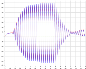
When our system is connected and DEMO CODE is burned on it, I read the UPS, DNS from the code and draw it using Python and get a normal signal:

When our system is connected and a TEMPLATE CODE is written on it, I read the UPS, DNS from the code and draw it using Python and get a bad signal:


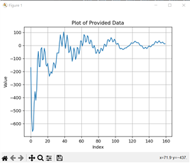
What could be the difference between them? why is it happening?
1) Could it be that I don't transmit at all when I use the TEMPLATE CODE? Because it seems there is no signal at all...
2) Could it be that I am transmitting something and I just don't catch it?

  • Hi Ido,

    Sorry for the slow response here.

    So you are using the unedited template code programmed to your custom device in the second image, and you are running the unedited demo code on the EVM430-FR6043 in the first image, correct?

    The difference could come from a few places. There could be an actual hardware difference causing this. Have you checked your design against the EVM design files as I mentioned in previous threads? The TI design for the EVM is a very helpful resource when working on custom hardware designs. I'll link the design again here, where you can find schematics, PCB layout, assembly drawing, and more.

    If you have changed the software in the examples that could also be a source for the issue. You should change the config file, as you mentioned, to get the correct excitement for your transducers, but until you've resolved the issue, you should leave the rest of the software similar, or the same.

    The next point is how are you interpreting your data? The default template example sends the upstream time of flight, the downstream time of flight, the delta time of flight, and the volume flow rate, sequentially, over and over again. If your second plot is intended to show the ADC capture values, like how the demo code does, you'd need to edit the template example to save all of the ADC capture values in a buffer, then send them out via UART. Considering the MSP430FR50431 samples at 8MHz, with 12 bits per sample, sending that buffer would take a very long time using UART, and you'd need to either spread the USS measurements out more to account for this, or add some scheme to save and send all of the data without collisions. Have you done this? 

    My point is, there are many places where this problem could occur, you need to be able to isolate the source in order to resolve it. Try swapping parts, adjusting your parameters, stepping through the code and debugging, to find where the problem lies, and then even if you are unable to find it at first, you can provide more information to those working to assist you, and I'll be able to help you more as well.

    I realize after all of this typing I may not be clearly answering your 2 direct questions:

    1) It is possible that you are not transmitting, are you checking the codes returned by the USS functions to see if there are errors? Do you have some other way to check to see if the ultrasonic signal is produced?

    2) This is possible, and you could check similarly to the above, as well as increasing the ADC capture duration and changing the time between pulse start and ADC capture to see if you can capture part of the waveform. Then maybe it will be clear if you are just not catching it at the correct time.

**Attention** This is a public forum