MSP430FR6047: water meter calibration

Part Number: MSP430FR6047
Other Parts Discussed in Thread: MSP430WARE

Tool/software:

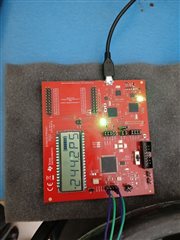
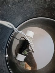
I need a help on water meter calibration part and we are using msp430fr6047 EVB along with audiowell ultrasonic sensors.

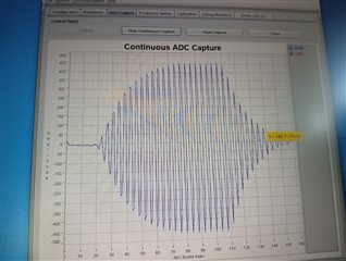
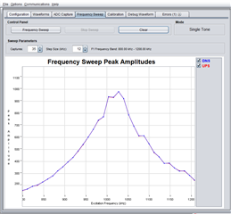
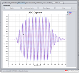
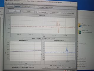
This is waveform we got from board.
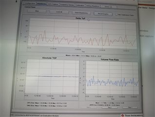
  • Hi Lakshmi,

    Your ADC capture looks good. The amplitude is around 450 codes, if possible try increasing your programmable gain in the GUI to get the amplitude near 900 codes.

    Your delta ToF looks pretty good as well. I assume this is in a zero flow environment? If so, you can apply a delta ToF offset of about 55-60 units to get your delta ToF closer to 0.

    You will likely find the USS Academy Module to be quite helpful for your early work with the device.

  • Hi Dylan OBrien,

    Thanks for your response I adjusted the programmable gain and got the 900 codes of amplitude. Later I tested standard deviation test I got standard deviation of the delta ToF waveforms in between 25PS to 50PS. 

    Now I am facing issue with Zero flow drift testing i.e., the Delta ToF values are continuously varying with positive and negative values.

    Here I am attaching waveforms.csv file for your reference. Please analyse the data and provide further help on this.

    waveforms6.csv

    waveforms7.csv

    waveforms8.csv

    Thanks,

    Lakshmi.

  • Lakshmi,

    Would it be possible for you to post images of your waveform plots? I am unable to download and view those files.

    Is there anything about your hardware set-up that is changing that may result in the continuously varying positive and negative dToF offsets? In my experience, I have always seen the dToF offset remain the same for a given device + pipe + transducer set up.

    As a side note, your ADC capture looks great, and your waveforms also look good. Glad to see you've conducted a frequency sweep as well, if you need any clarification on what to do with the frequency sweep data please let me know and I can offer advice there.

  • Thanks for the response Dylan OBrien,

    I filled a ice cubes with bowl and placed the sensor inside the bowl. I checked the temperature i.e.., 5 degree Celsius gradually increasing the temperature and observed the delta ToF values in waveforms.csv as well as in the display it's continuously varying from positive to negative.

    Here I am attached the setup images and video.


  • So in your original testing where you mention that you got a standard deviation of 25-50ps, was that with zero flow in the pipe?

    Depending on the environmental conditions, the fluctuations you are seeing are not necessarily out of the ordinary. A few hundred ps could certainly be due to some environmental noise factors. 

    I see in one of your images, the pipe is sitting in a still bowl of water. While this can be low flow, you may want to try placing caps on the ends of the tube to enclose the water, and make sure it is more still. I also wonder if in your end application, you plan for the tube and transducers to be submerged in water? If that is accurate to your end application then you are welcome to continue doing so, I am just curious.

    Is there noise in the environment from other factors, such as nearby motors? This can also affect measurements.

    I can also see that the average dToF is about -200 ps, you should try factoring that into your dToF offset for the most accurate possible data.

    To summarize, I would recommend that you try some small additions to reduce environmental noise, and to ensure zero flow, and continue testing, to ensure that you have the lowest possible flow, and the least noise possible, when calibrating the device. In the end this will help to ensure accurate calibration and to get a better baseline device behavior so that you can better evaluate its performance in more rigorous field testing later on.

  • Hi thanks for the responce,

    I tried to debug the code by adding the prints in demo code. But the prints are not coming. So, Please guide me how to debug the code.

  • You can also insert hardware breakpoints to check the status of the device at various points in your code. How are you implementing the prints, can you show me an example? Are you just using UART out? This is fine but it may be easiest to start with hardware breakpoints to review how the code is functioning.

  • Thanks for the response.

    I added #include<stdio.h> in file still i am getting the debug prints i added hardware breakpoints also in code but no luck. Here i attached the snap shot how i added prints in main.c. So, Please guide me how to debug the code in CCS.

  • printf() will not be able to print text to your console from the MSP. You will need to output these messages using a communication protocol like UART. You can achieve a similar functionality to the printf() function by sending those debug messages using the backchannel UART, and then using a terminal emulator program such as PuTTY or termite. You can see examples of using the backchannel UART in the MSP430Ware SDK, and we have some walkthroughs of this in the MSP Academies for other devices that will work similarly. 

**Attention** This is a public forum